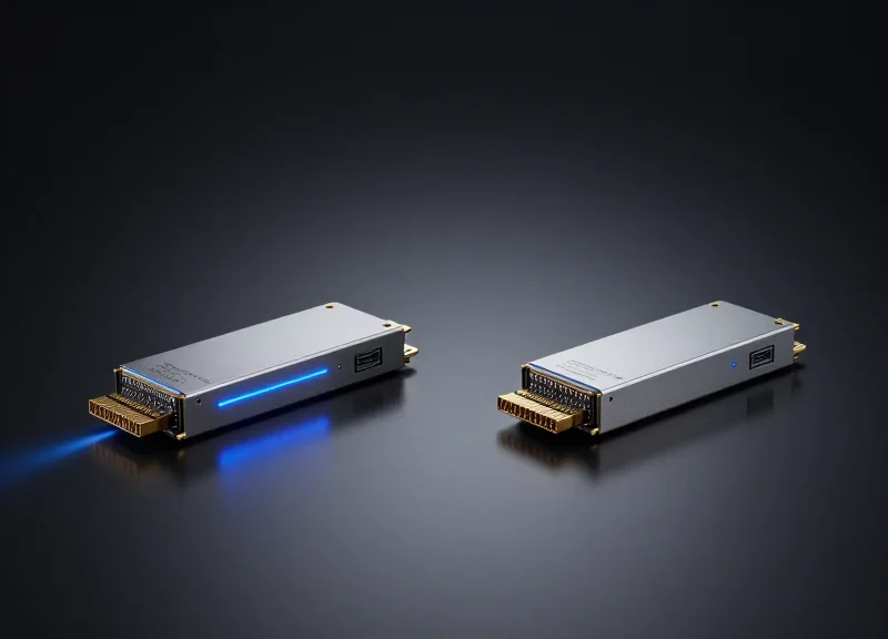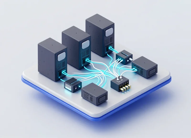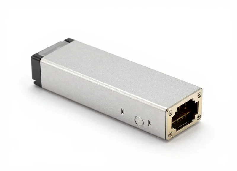
As data centers and enterprise networks transition to higher bandwidths, the 100G QSFP28 LR4 transceiver has emerged as a critical component for long-reach connectivity. Operating over single-mode fiber with a reach of up to 10km, this technology leverages sophisticated wavelength division multiplexing to deliver reliable performance. This deep dive explores the technical architecture, standards, and practical considerations for deploying 100G LR4 in modern infrastructure.
Defining 100G LR4: The IEEE 802.3ba Standard

Defining 100G LR4: The IEEE 802.3ba Standard
100G LR4 is a high-speed optical interface specification defined by the IEEE 802.3ba task force to provide 100 Gigabit Ethernet (100GbE) connectivity over distances up to 10 kilometers. It utilizes Wavelength Division Multiplexing (WDM) technology to transmit four separate 25Gbps channels simultaneously over a single pair of single-mode fibers. This standard was revolutionary for metropolitan area networks (MANs) and large-scale data centers, as it provided a standardized, interoperable method for long-reach high-bandwidth communication without the need for expensive signal regeneration.
Decoding the LR4 Nomenclature
The 'LR4' suffix is not just a marketing label; it describes the specific physical layer (PHY) characteristics of the transceiver. Understanding these components is essential for network engineers planning long-haul infrastructure.
| Designation | Technical Meaning |
|---|---|
| L | Long Reach: Specifies a maximum transmission distance of 10km. |
| R | Referencing the 64B/66B encoding used for the physical coding sublayer. |
| 4 | Indicates that the 100G signal is multiplexed into four distinct wavelengths. |
Optical Wavelengths and LAN WDM
To achieve 100Gbps throughput, the IEEE 802.3ba standard specifies the use of Local Area Network Wavelength Division Multiplexing (LAN WDM). The 100G LR4 transceiver operates on four specific wavelengths within the O-band, which is characterized by zero dispersion. These wavelengths are 1295.56nm, 1300.05nm, 1304.58nm, and 1309.14nm. By spacing these wavelengths approximately 4.5nm apart, the standard ensures minimal crosstalk and high signal integrity over the 10km link.
Core Technical Specifications
- What fiber type is required for 100G LR4?
100G LR4 is designed exclusively for Single-Mode Fiber (SMF), specifically G.652 standard fiber, which supports the narrow laser beams required for long-distance transmission. - Is Forward Error Correction (FEC) mandatory?
Under the IEEE 802.3ba standard, 100GBASE-LR4 is designed to operate with a very low Bit Error Rate (BER) of 10^-12, meaning it does not strictly require FEC for standard 10km links, unlike many newer 100G standards. - What are the power consumption standards?
The IEEE 802.3ba standard and subsequent MSA agreements (like QSFP28) aim for high efficiency, typically limiting 100G LR4 transceivers to a power envelope of 3.5W to 4.5W depending on the form factor.
By adhering to the IEEE 802.3ba standard, 100G LR4 equipment ensures multi-vendor interoperability. This means a network administrator can pair a Cisco-coded 100G LR4 transceiver on one end of a link with a Juniper-coded module on the other, provided both strictly follow the 802.3ba technical parameters for power levels and wavelength accuracy.
The Science of LAN-WDM Wavelengths
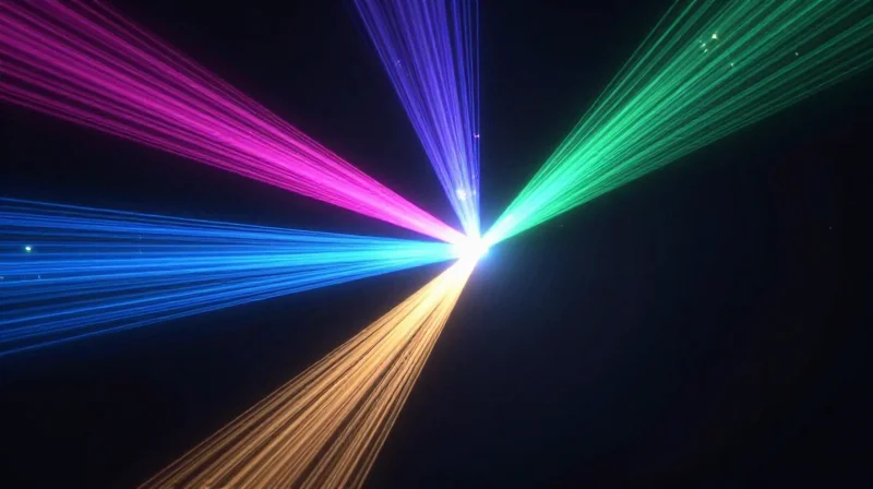
100G LR4 technology achieves its 10km reach by multiplexing four specific wavelengths in the 1310nm window, a strategy designed to capitalize on the low chromatic dispersion characteristics of G.652 single-mode fiber.
The LAN-WDM Wavelength Grid Precision
The selection of the LAN-WDM grid is a deliberate engineering choice to combat the physical limitations of light transmission at 100Gbps. By utilizing a narrow frequency spacing of 800GHz (approximately 4.5nm), all four optical channels are kept within the O-band (Original Band). This is critical because the O-band contains the zero-dispersion wavelength for standard single-mode fiber, meaning the optical pulses experience minimal spreading as they travel the 10km distance.
| Channel Designation | Center Wavelength | Frequency (THz) | Wavelength Range (nm) |
|---|---|---|---|
| L0 | 1295.56 nm | 231.4 | 1294.53 to 1296.59 |
| L1 | 1300.05 nm | 230.6 | 1299.02 to 1301.09 |
| L2 | 1304.58 nm | 229.8 | 1303.54 to 1305.63 |
| L3 | 1309.14 nm | 229.0 | 1308.09 to 1310.19 |
Mitigating Chromatic Dispersion and Signal Jitter
In 100G transmission, each of the four lanes carries 25.78 Gbps of data. At these high speeds, chromatic dispersion—where different spectral components of a signal travel at different velocities—can cause severe Inter-Symbol Interference (ISI). While CWDM4 uses a 20nm spacing that stretches further away from the zero-dispersion point, LAN-WDM's tight cluster near 1310nm ensures that all lanes arrive at the receiver with high temporal alignment, effectively eliminating the need for complex Dispersion Compensation Modules (DCMs).
- Why does 100G LR4 require TEC cooling?
Because the LAN-WDM channels are spaced only 4.5nm apart, even slight temperature fluctuations can cause wavelength drift and crosstalk. Thermo-Electric Coolers (TEC) are integrated into the TOSA to stabilize the laser frequency. - How does LAN-WDM compare to CWDM for 10km links?
CWDM is optimized for cost and short distances (up to 2km), but its higher dispersion penalty makes it unreliable for 10km 100G links, where LAN-WDM is the industry standard for performance. - Is the signal quality better in the O-band?
Yes, the O-band provides the optimal balance of low attenuation and near-zero dispersion for single-mode fiber, which is essential for maintaining the high Signal-to-Noise Ratio (SNR) required for 10km reach.
Inside the Module: TOSA, ROSA, and MUX/DEMUX
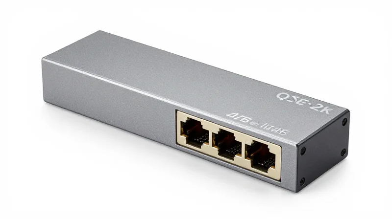
The 100G LR4 QSFP28 module is a masterpiece of optoelectronic engineering, housing a complex array of components that facilitate the conversion between electrical signals and optical pulses across four distinct wavelengths. Central to this process are the Transmitter Optical Sub-Assembly (TOSA), which generates the light, and the Receiver Optical Sub-Assembly (ROSA), which detects it. These assemblies work in tandem with optical multiplexers (MUX) and demultiplexers (DEMUX) to aggregate four 25Gbps lanes into a single 100Gbps stream over single-mode fiber.
The TOSA: Precision Laser Generation
In a 100G LR4 module, the TOSA typically contains four Distributed Feedback (DFB) lasers. Each laser is tuned to one of the specific LAN-WDM wavelengths (1295.56nm to 1309.14nm). Because 100G LR4 is designed for 10km reaches, these lasers must maintain high output power and spectral purity. To prevent wavelength drift caused by temperature fluctuations, these modules often include an internal Thermo-Electric Cooler (TEC), ensuring the lasers remain within their tight 800GHz frequency grid despite the heat generated by the dense QSFP28 form factor.
The ROSA: Sensitivity and Conversion
The Receiver Optical Sub-Assembly (ROSA) sits at the opposite end of the link. It consists of four PIN photodiodes and a Transimpedance Amplifier (TIA). The ROSA's primary task is to receive the incoming multiplexed light, which has been separated by the DEMUX, and convert the photons back into electrical current. The sensitivity of the ROSA is critical for the 10km reach, as it must accurately interpret signals that have undergone attenuation and dispersion over the fiber span. High-quality TIAs are employed to amplify these signals while maintaining a high signal-to-noise ratio.
Optical MUX and DEMUX: The Traffic Controllers
Without the Multiplexer (MUX) and Demultiplexer (DEMUX), the four discrete optical signals would require four separate fiber pairs. In a 100G LR4 module, the MUX uses thin-film filters or silica-based waveguides to combine the four 25G LAN-WDM signals into a single output port. Conversely, the DEMUX at the receiving end splits the incoming aggregate signal back into its four constituent wavelengths before passing them to the ROSA. This architectural efficiency allows the 100G link to operate over a standard duplex LC single-mode fiber pair.
| Component | Primary Function | Key Technologies |
|---|---|---|
| TOSA | Electrical-to-Optical Conversion | DFB Lasers, TEC Cooler |
| ROSA | Optical-to-Electrical Conversion | PIN Photodiodes, TIA |
| MUX/DEMUX | Wavelength Management | Thin Film Filters (TFF) |
Hardware Comparison & FAQ
- Why does 100G LR4 use DFB lasers instead of VCSELs?
DFB lasers provide the higher optical power and narrow spectral width required for 10km single-mode fiber transmission. VCSELs are typically limited to short-reach multi-mode fiber applications. - Is the MUX/DEMUX passive or active?
The optical MUX/DEMUX filters themselves are passive components, but they are integrated into the active transceiver housing to manage the signal flow. - What is the role of the TEC in the TOSA?
The Thermo-Electric Cooler (TEC) stabilizes the laser temperature, which is vital because LAN-WDM wavelengths are very close together and sensitive to thermal drift.
Key Performance Specifications: Power Budget and Sensitivity

Defining the 100G LR4 Optical Link Budget
The success of a 100G LR4 link depends on the precise balance between the launched optical power from the Transmitter Optical Sub-Assembly (TOSA) and the detection capability of the Receiver Optical Sub-Assembly (ROSA). For a standard 10km reach over G.652 single-mode fiber, the IEEE 802.3ba standard mandates a minimum power budget of 6.3 dB. This budget must account for fiber attenuation, connector insertion loss, and the dispersion penalties inherent in high-speed 25Gbps per-lane transmission.
Transmitter Power and Receiver Sensitivity
A typical 100G LR4 QSFP28 module operates with four LAN-WDM lanes, each transmitting at approximately 25.78 Gbps. The transmitter power for each individual lane usually ranges from -4.3 dBm to +4.5 dBm. On the receiving end, the 'Receiver Sensitivity' is the most critical metric; the ROSA must be able to resolve signals as low as -10.6 dBm (at a Bit Error Rate of 1x10^-12) to maintain the integrity of the 10km link without requiring external amplification.
| Parameter | Specification (Per Lane) | Total Aggregate (Typical) |
|---|---|---|
| Transmit Power (Max) | +4.5 dBm | +10.5 dBm |
| Transmit Power (Min) | -4.3 dBm | +1.7 dBm |
| Receiver Sensitivity (Max) | -10.6 dBm | N/A |
| Receiver Overload | +4.5 dBm | N/A |
| Optical Return Loss Tolerance | 20 dB | N/A |
Managing Link Loss and Operating Margins
Calculating the effective power budget involves subtracting the receiver sensitivity from the minimum transmit power. For LR4, -4.3 dBm (min TX) minus -10.6 dBm (min RX) equals a 6.3 dB total budget. In a real-world 10km deployment, fiber attenuation typically accounts for 3.5 dB (calculated at 0.35 dB/km), leaving approximately 2.8 dB for patch panel connectors, fusion splices, and safety margins. If the total channel loss exceeds 6.3 dB, the link will experience high Bit Error Rates (BER) or fail to link up entirely.
- What happens if the TX power is too high?
If the received power exceeds the 'Receiver Overload' threshold (typically +4.5 dBm), the photodiode in the ROSA can saturate. This leads to signal clipping and bit errors. In very short test runs, an optical attenuator is required to protect the receiver. - Does 100G LR4 require Forward Error Correction (FEC)?
The original IEEE 802.3ba 100GBASE-LR4 standard was designed to operate at a BER of 10^-12 without FEC. However, many modern QSFP28 LR4 modules are used on hosts with RS-FEC (528,514) enabled to provide additional link margin and robustness. - How does the LAN-WDM grid affect the budget?
Because the LAN-WDM wavelengths are placed near the zero-dispersion point of SMF, the 'Dispersion Penalty' is kept low (typically around 2.2 dB), ensuring that the power budget is used primarily to overcome distance rather than signal distortion.
Comparative Analysis: 100G LR4 vs. CWDM4 vs. PSM4
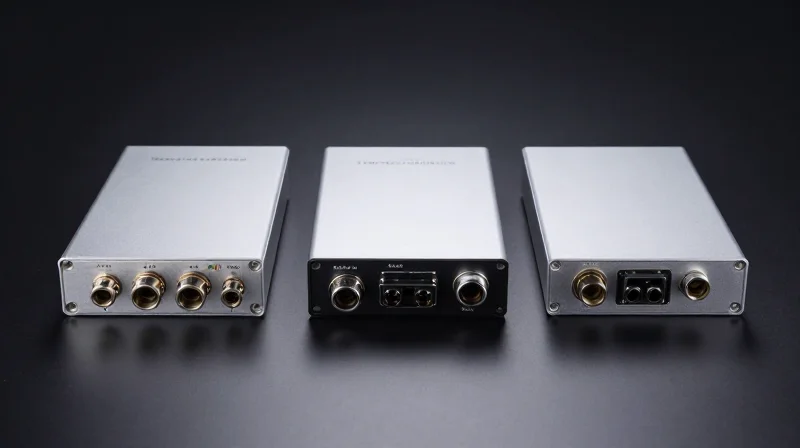
Comparative Analysis: 100G LR4 vs. CWDM4 vs. PSM4
Determining the optimal 100G transceiver requires a strategic evaluation of transmission distance and cabling complexity, with the 100G LR4 standing out as the definitive solution for high-performance 10km links over existing duplex single-mode fiber. While CWDM4 and PSM4 provide economical alternatives for data center interconnects, they cannot match the link budget or the spectral precision of the LR4's LAN-WDM architecture, which is specifically engineered to minimize chromatic dispersion over longer distances.
| Specification | 100G LR4 | 100G CWDM4 | 100G PSM4 |
|---|---|---|---|
| Standard Reach | 10 km | 2 km | 500 m - 2 km |
| Fiber Type | Duplex Single-Mode | Duplex Single-Mode | Parallel Single-Mode (8/12-core) |
| Connector Type | LC Duplex | LC Duplex | MPO-12 |
| Wavelengths | 1295, 1300, 1305, 1310nm | 1271, 1291, 1311, 1331nm | 1310nm (4 lanes) |
| Modulation | NRZ | NRZ | NRZ |
| Laser Source | EML or DML (Cooled) | DML (Uncooled) | DML (Uncooled) |
Architectural Differences: LAN-WDM vs. CWDM vs. Parallel Fiber
The primary differentiator between these modules lies in how they manage optical lanes. 100G LR4 uses a LAN-WDM grid with a narrow 4.5nm channel spacing. This proximity to the zero-dispersion point allows the signal to travel 10km without significant distortion. In contrast, 100G CWDM4 uses a wider 20nm spacing, which is simpler and cheaper to manufacture but limits the reach to 2km due to increased dispersion. 100G PSM4 bypasses multiplexing entirely by using an MPO connector to send four independent 25G signals over eight fibers. While the optics for PSM4 are the least expensive, the requirement for eight times the fiber makes it costly for long-distance runs.
Use Case Optimization
For campus backbones and metropolitan area networks (MAN), the 100G LR4 is the industry standard because it utilizes the standard duplex LC fiber pairs already found in most patch panels. CWDM4 is the preferred 'sweet spot' for intra-data center links that exceed the 100m limit of multi-mode fiber but do not require the full 10km reach. PSM4 is uniquely suited for high-density environments where 'breakout' applications are needed, such as connecting one 100G switch port to four individual 25G servers using a breakout cable.
Selection FAQ: Choosing the Right Interface
- Can I connect a 100G LR4 module to a 100G CWDM4 module?
No. Even though both use LC connectors and single-mode fiber, their wavelength grids are fundamentally different. The receiver on a CWDM4 module cannot properly filter the LAN-WDM wavelengths transmitted by an LR4 module. - Why is 100G LR4 more expensive than PSM4?
LR4 requires complex optical multiplexers (MUX/DEMUX) and often requires cooled lasers to maintain the precise LAN-WDM wavelengths, whereas PSM4 uses a simpler parallel design without multiplexing components. - Does 100G LR4 support 4x25G breakout?
Generally, no. Because the four wavelengths are multiplexed into a single fiber pair, you cannot easily split them into four separate physical 25G ports. PSM4 is the primary choice for breakout scenarios.
Cabling and Connectivity: SMF and LC Duplex
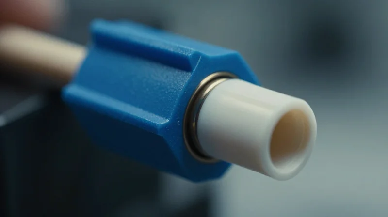
The physical layer connectivity for 100G LR4 is defined by its use of Single-Mode Fiber (SMF) and the standardized LC duplex interface. Unlike short-reach multi-mode solutions, LR4 leverages the narrow core of SMF to eliminate modal dispersion, allowing the four LAN-WDM optical signals to travel up to 10 kilometers with minimal attenuation. This infrastructure requirement is a cornerstone of long-haul data center interconnects and enterprise backbone cabling.
Single-Mode Fiber Requirements (G.652)
The 100G LR4 standard is optimized for G.652 single-mode fiber, specifically the G.652.D sub-category. This fiber type is characterized by its 'low water peak' performance, which ensures that the attenuation remains low across the entire E-band and S-band. For LR4, which operates around the 1310nm zero-dispersion window, G.652 fiber provides the ideal balance of low chromatic dispersion and low insertion loss.
| Parameter | SMF (G.652.D) Specification | Impact on 100G LR4 |
|---|---|---|
| Core Diameter | ~9 µm | Ensures single-mode propagation and prevents modal noise. |
| Attenuation (1310nm) | ≤ 0.35 dB/km | Determines the maximum reach within the optical power budget. |
| Dispersion Slope | ≤ 0.092 ps/(nm²·km) | Minimizes pulse spreading for the four LAN-WDM wavelengths. |
| Connector Type | LC Duplex | Standardized interface for QSFP28 and CFP2 modules. |
The LC Duplex Connector Interface
100G LR4 transceivers utilize the LC duplex connector as the primary interface. The LC connector is a Small Form Factor (SFF) interface that uses a 1.25mm ceramic ferrule. In an LR4 configuration, one fiber of the duplex pair acts as the transmit path (Tx) and the other as the receive path (Rx). Because the multiplexing and demultiplexing of the four 25Gbps wavelengths happen inside the transceiver module, only two fibers are needed for the full 100Gbps link.
Connector Polarity and Cleaning
Maintaining proper polarity (Tx to Rx) is essential in LC duplex cabling. Furthermore, due to the high sensitivity of LR4 ROSA components, connector cleanliness is paramount. Even microscopic debris on an LC ferrule can cause back-reflections (ORL) that destabilize the laser or cause bit errors. It is recommended to use UPC (Ultra Physical Contact) polished connectors as the standard, though some specialized environments may utilize APC (Angled Physical Contact) to further reduce reflections.
- Can 100G LR4 run over OM3/OM4 fiber?
No. 100G LR4 requires single-mode fiber (9/125µm). Multi-mode fiber has a much larger core that causes massive modal dispersion, rendering the LR4 signal unreadable within a few meters. - Is an MPO-to-LC breakout cable needed for LR4?
No. Unlike 100G SR4 or PSM4 which use MPO interfaces, 100G LR4 has internal WDM filters and uses a standard LC duplex patch cord. - What is the maximum patch cord length recommended?
While the transceiver supports 10km, patch cords are typically short (1-5m). The total link length, including the horizontal/backbone cabling and all patch leads, must stay within the 10km / 6.3dB power budget.
Primary Use Cases: DCI and Metro Core Networks
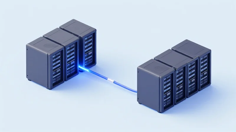
Primary Use Cases: DCI and Metro Core Networks
The 100G LR4 10km standard is engineered to provide a robust, high-bandwidth link that bridges the gap between short-range intra-datacenter connections and long-haul telecommunications. By utilizing four WDM wavelengths over a single pair of single-mode fibers, it enables network architects to extend 100Gbps throughput across city-wide distances without the need for expensive amplification or complex dispersion compensation.
Data Center Interconnect (DCI) and Hyper-scale Facilities
In the era of cloud computing, many organizations operate multiple data center facilities within a 10km radius to ensure redundancy and load balancing. The 100G LR4 transceiver is the industry standard for these 'east-west' traffic flows. It allows for seamless high-speed synchronization of databases and real-time data mirroring between sites, ensuring that if one facility goes offline, the other can take over with minimal latency impact. Its reach is perfectly suited for regional 'availability zones' where distance-related latency must be kept under 1ms.
Campus and Enterprise Backbone Infrastructure
For large university campuses or sprawling corporate headquarters, the 100G LR4 is used to create a high-capacity backbone connecting separate buildings. Unlike multi-mode solutions like SR4 that are limited to 100 meters, LR4 utilizes existing G.652 single-mode fiber plants to provide a future-proof 100G uplink from distribution switches to the core network. This supports data-intensive operations such as high-definition video surveillance, large-scale research data transfers, and Virtual Desktop Infrastructure (VDI).
| Application | Reach Requirement | Primary Benefit |
|---|---|---|
| DCI (Regional) | 5km - 10km | Low-latency data mirroring between regional nodes |
| Metro Core | 8km - 10km | Cost-effective 100G aggregation for ISP backhaul |
| Campus Backbone | 2km - 10km | High-bandwidth trunking between dispersed buildings |
Telecommunication and Metro Carrier Networks
Carrier networks leverage 100G LR4 at the metro edge to aggregate traffic from multiple access points. It serves as a cost-effective alternative to coherent optics for distances under 10km, allowing Internet Service Providers (ISPs) to scale their 5G fronthaul and backhaul architectures. By utilizing the 1310nm window, LR4 minimizes the impact of chromatic dispersion, ensuring high signal integrity over the standard single-mode fiber (SMF) common in metropolitan environments.
- Can 100G LR4 be used for distances shorter than 2km?
Yes, but if the fiber link is very short (e.g., <500m), you must check the receiver power levels. An optical attenuator might be required to prevent the high-power laser from saturating or damaging the receiver photodiode. - Is LR4 compatible with existing G.652 fiber?
Absolutely. LR4 is specifically optimized for G.652 single-mode fiber, which is the most widely deployed fiber type in metro and campus environments globally. - Why choose LR4 over CWDM4 for 2km links?
While CWDM4 is cheaper for 2km, LR4 offers a more robust link budget (approx 6.3dB), making it more reliable in environments with many patch panels or older fiber with higher splice loss.
Power Consumption and Thermal Management
Power Consumption and Thermal Management
The 100G LR4 QSFP28 transceiver is engineered to operate within a specific power envelope, typically categorized as a Power Class 4 device with a maximum consumption of 3.5W. This power profile is higher than that of short-reach modules like the SR4 or CWDM4 because the LR4 utilizes four EML (Electro-absorption Modulated Laser) transmitters and complex LAN-WDM optical multiplexers. These components require precise voltage and cooling to maintain the narrow wavelength spacing necessary for 10km reaches over single-mode fiber. Efficient thermal management is not merely a preference but a technical requirement; excessive heat directly impacts the laser's spectral stability and can lead to bit error rate (BER) degradation or premature hardware failure.
The 3.5W Power Envelope and QSFP28 Standards
According to the QSFP28 Multi-Source Agreement (MSA), modules are divided into power classes to help system designers allocate sufficient cooling and electrical budget per port. The 100G LR4 consistently falls into the upper tier of these classes. The power is primarily consumed by the internal CDR (Clock and Data Recovery) chips and the TEC (Thermo-Electric Cooler) used in some high-performance LR4 variants to stabilize the EML lasers against ambient temperature fluctuations.
| Power Class | Max Power (Watts) | Typical 100G Module Types |
|---|---|---|
| Class 1 | 1.5W | 100G DR/FR (Single Lambda) |
| Class 2 | 2.0W | 100G SR4 |
| Class 3 | 2.5W | 100G CWDM4 |
| Class 4 | 3.5W | 100G LR4 / ER4 Lite |
Thermal Efficiency in High-Density Environments
In a high-density switch environment—such as a 1RU leaf switch with 32 or 48 QSFP28 ports—the cumulative heat generated by 100G LR4 modules can exceed 100 Watts from the optics alone. This necessitates robust airflow management. Systems must ensure that the 'case temperature' of the LR4 module remains within the standard commercial range (0°C to 70°C). If the case temperature exceeds these limits, the internal laser bias currents increase to compensate for efficiency loss, creating a thermal runaway loop that can permanently damage the optical sub-assembly (OSA).
- Why does LR4 consume more power than SR4?
LR4 uses EML lasers and complex WDM optical mux/demux components that require more drive current and thermal stabilization than the VCSELs used in SR4 modules. - How does heat affect 10km transmission?
Excessive heat causes wavelength drifting. Since LR4 uses the narrow LAN-WDM grid, even a slight shift in wavelength can cause the signal to fall outside the filter's passband, resulting in high signal loss. - What are the cooling requirements for LR4?
Switches must provide adequate CFM (Cubic Feet per Minute) of airflow. In many chassis, front-to-back cooling is used to ensure fresh air hits the transceiver faceplates first.
Future-Proofing: Transitioning from 100G to 400G
The Migration Path from 100G LR4 to 400G LR4
Transitioning from 100G LR4 to 400G LR4 is a critical step for data centers and telecommunications providers looking to quadruple their bandwidth while leveraging existing single-mode fiber (SMF) infrastructure. While 100G LR4 relies on Non-Return-to-Zero (NRZ) modulation across four 25Gbps lanes, the 400G LR4 standard typically utilizes Pulse Amplitude Modulation 4-level (PAM4) to achieve 100Gbps per lane. This evolution allows operators to maintain the same 10km reach over LC duplex connectors while significantly improving bit-per-watt efficiency and rack density.
| Feature | 100G LR4 | 400G LR4 |
|---|---|---|
| Modulation | NRZ | PAM4 |
| Data Lanes | 4 x 25Gbps | 4 x 100Gbps |
| Form Factor | QSFP28 | QSFP-DD / OSFP |
| Optical Reach | 10km (SMF) | 10km (SMF) |
| Standard Power | 3.5W - 4.5W | 10W - 12W |
Technical Evolution: From NRZ to PAM4
The most significant technical hurdle in the transition is the move from NRZ to PAM4 signaling. 100G LR4 modules use simple binary signaling, which is robust but limited in spectral efficiency. 400G LR4 adopts PAM4, which carries two bits of information per symbol. While PAM4 is more susceptible to noise—requiring Forward Error Correction (FEC)—it is the primary mechanism that enables 400G to operate over the same four-wavelength WDM grid used by legacy 100G systems, ensuring fiber plant longevity.
Infrastructure Readiness and Backward Compatibility
Future-proofing a network built on 100G LR4 involves ensuring that new hardware supports backward compatibility. Most QSFP-DD ports are designed to be backward compatible with QSFP28 modules, allowing for a phased migration. Operators can deploy 400G-capable switches today, continue using 100G LR4 transceivers for existing links, and swap to 400G LR4 modules as traffic demands increase, all without replacing the underlying G.652 single-mode fiber cabling.
- Can I connect a 100G LR4 module to a 400G LR4 module directly?
No, they are not directly interoperable due to different modulation schemes (NRZ vs. PAM4) and lane speeds. A gearbox or a protocol-matching switch is required to bridge these two generations. - Does 400G LR4 require different fiber than 100G LR4?
No, both standards are designed for G.652 single-mode fiber (SMF) using LC duplex connectors, making the 400G upgrade a 'plug-and-play' transition for the physical cable plant. - What is the primary benefit of upgrading to 400G LR4?
Beyond the 4x increase in throughput, 400G LR4 reduces the total cost per bit and lowers the power consumption per gigabit compared to running four separate 100G links.
Understanding the technical nuances of 100G LR4 is essential for building a resilient, high-performance optical network. Whether you are upgrading a data center or expanding a metro link, 100G LR4 offers the perfect balance of distance and reliability. Explore our range of TAA-compliant transceivers or consult with our experts today to find the ideal solution for your 10km connectivity needs.