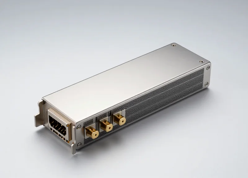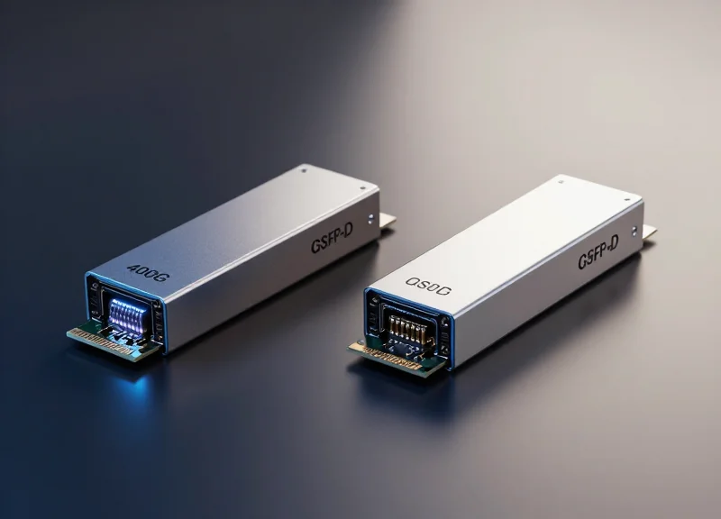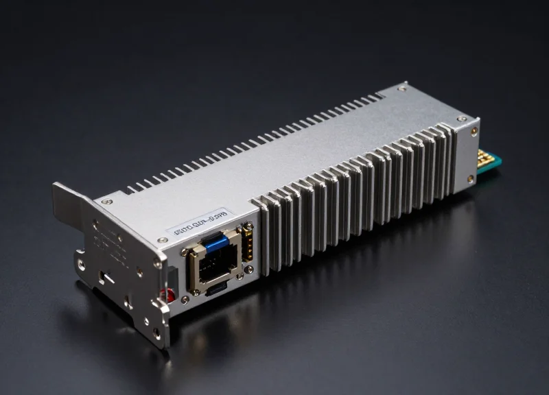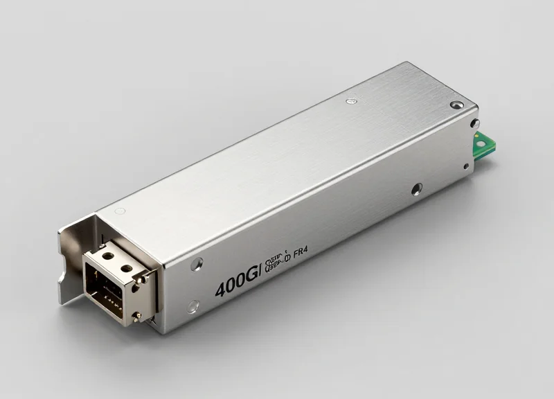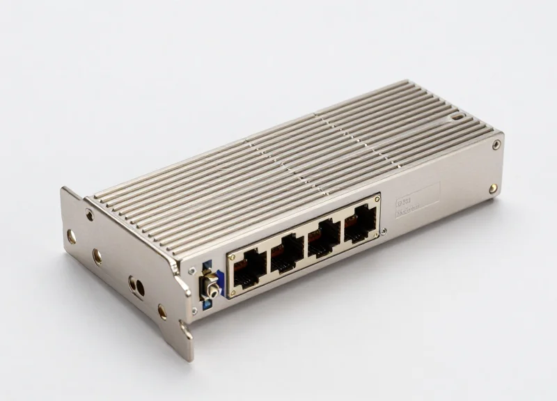
The explosion of AI-driven traffic and the rise of Large Language Models (LLMs) have pushed data center bandwidth requirements to their limits. As 800G becomes the new standard for backbone connectivity, the OSFP 2xFR4 optical module has surfaced as a pivotal technology, offering a unique blend of high density and proven 400G maturity. In this technical deep dive, we explore how this dual-engine transceiver architecture optimizes high-speed optical networks.
Evolution of High-Speed Optics: The Road to 800G

The transition to 800G optics represents a critical milestone in optical networking, moving beyond the limitations of 400G to satisfy the exponential growth in data traffic. This evolution is primarily enabled by the maturation of 100G-per-lane SerDes technology, allowing for 800G throughput within a single module. As hyperscale environments struggle with power efficiency and physical space, the shift toward 800G—specifically utilizing the OSFP form factor—provides the necessary density and thermal management to support next-generation switching silicon like the 51.2Tbps generation.
The Market Shift: Why 400G is No Longer Enough
While 400G modules revolutionized the data center for several years, the emergence of Large Language Models (LLMs) and massive distributed computing has created a 'bandwidth gap.' The industry is pivoting to 800G to minimize the number of optical interfaces required for a given capacity, thereby reducing complexity and potential points of failure.
| Metric | 400G Generation | 800G Generation |
|---|---|---|
| Per-lane Rate | 50G PAM4 / 100G PAM4 | 100G PAM4 / 200G PAM4 (Emerging) |
| Total Throughput | 400 Gbps | 800 Gbps |
| Typical Form Factor | QSFP-DD / OSFP | OSFP / QSFP-DD800 |
| Switch Silicon Capacity | 12.8T to 25.6T | 51.2T to 102.4T |
Drivers for 800G OSFP Adoption
The adoption of 800G is not merely about speed; it is about density and cooling. The OSFP (Octal Small Form-factor Pluggable) design, with its integrated heat sink, has gained significant traction over legacy form factors because it can dissipate the 15-20 watts of power typically required by 800G DSPs.
- How does AI affect the road to 800G?
AI workloads require massive East-West traffic between GPU clusters. 800G reduces the latency and physical cabling required to interconnect these nodes compared to using multiple 400G links. - Why is port density critical for hyperscalers?
Hyperscalers need to maximize the throughput of every rack unit. 800G allows for up to 32 ports of 800G in a 1U chassis, doubling the bandwidth of previous 400G configurations. - What is the role of 2xFR4 in this evolution?
The 2xFR4 architecture allows for a seamless transition by providing two independent 400G interfaces in a single 800G module, offering a bridge between current 400G infrastructure and the 800G future.
The 2xFR4 Architecture: Understanding the Dual-Engine Design

The 800G OSFP 2xFR4 architecture is defined by its 'twin-engine' design, integrating two independent 400G FR4 optical assemblies into a single high-density transceiver module. By utilizing two distinct sets of four CWDM wavelengths (1271, 1291, 1311, and 1331nm) over two separate fiber pairs, this architecture delivers a total aggregate throughput of 800Gbps. This design choice allows hyperscale data centers to double their port density using established 100G PAM4 technology, avoiding the higher complexity and lower yields associated with early-stage 200G-per-lane optical components.
The Mechanics of the Dual-Engine Signal Path
In a 2xFR4 configuration, the host-side electrical interface consists of 8 lanes running at 106.25 Gbps (PAM4). Inside the module, these lanes are routed to a high-performance Digital Signal Processor (DSP) that manages two separate optical signal paths. Each path represents one 400G FR4 'engine' that performs electrical-to-optical conversion. These engines operate in parallel but are logically distinct, allowing the module to function either as a unified 800G link or as two independent 400G links, depending on the network equipment's port configuration.
| Technical Parameter | 800G OSFP 2xFR4 | 800G OSFP DR8 |
|---|---|---|
| Optical Engine Configuration | Dual 400G FR4 (2x4 CWDM) | Single 800G (8x100G Parallel) |
| Fiber Requirement | 2 Pairs (4 Fibers) | 8 Pairs (16 Fibers) |
| Wavelengths | 1271, 1291, 1311, 1331 nm | 1310 nm |
| Maximum Reach | 2 km (SMF) | 500 m to 2 km (SMF) |
| Connector Type | Dual LC or CS | MPO-12 or MPO-16 |
Operational Benefits of the 2xFR4 Design
The primary advantage of the 2xFR4 architecture is its superior fiber efficiency and backward compatibility. By multiplexing four signals onto a single fiber via Wavelength Division Multiplexing (WDM), it drastically reduces the amount of physical cabling required compared to parallel-fiber solutions like DR8. Furthermore, the OSFP form factor provides an optimized thermal path, ensuring that the heat generated by two 400G engines is effectively dissipated, maintaining stable performance across high-radix switch ports.
- Can 800G 2xFR4 break out into 400G FR4?
Yes, the 2xFR4 architecture is designed specifically to support breakout modes. It can interface with two separate 400G FR4 modules using a breakout cable, making it ideal for connecting new 800G spine switches to existing 400G leaf switches. - What is the difference between Dual LC and CS connectors in 2xFR4?
Dual LC connectors provide a standard interface for duplex fiber, while the CS connector is a smaller form factor that allows for even higher density and simplified breakout management within the OSFP patch panel. - Does 2xFR4 support KP4 FEC?
The module relies on the host's KP4 Forward Error Correction (FEC) to ensure data integrity across the 100G PAM4 lanes, maintaining a bit error rate (BER) within industry standards for 2km reaches.
Technical Specifications: Reach, Wavelengths, and Signaling
Technical Specifications: Reach, Wavelengths, and Signaling
The 800G OSFP 2xFR4 transceiver is a high-performance optical module engineered to deliver 800Gbps of aggregate throughput by leveraging two independent 400G FR4 engines. Unlike parallel fiber solutions like the DR8, the 2xFR4 utilizes Coarse Wavelength Division Multiplexing (CWDM) to transmit signals over 2km of Single-Mode Fiber (SMF), making it the primary choice for leaf-to-spine and campus-level interconnects where 500m reach is insufficient.
The 2km Reach Advantage over Single-Mode Fiber
The 800G 2xFR4 is specifically optimized for a 2-kilometer transmission distance. This reach is achieved using standard G.652 SMF, providing a cost-effective alternative to LR8 solutions which are designed for 10km. By targeting the 2km 'sweet spot,' data center operators can maintain high signal integrity without the extreme power consumption and thermal overhead associated with long-haul laser drivers. The use of dual Dual LC or MPO-12 connectors allows this reach to be utilized in high-density environments.
Core Optical and Electrical Parameters
| Parameter | Specification |
|---|---|
| Max Transmission Distance | 2km over SMF (G.652) |
| Wavelength Grid | CWDM4 (1271, 1291, 1311, 1331nm) |
| Modulation Format | 100G PAM4 (Pulse Amplitude Modulation) |
| Electrical Interface | 8x112Gbps (GAUI-8) |
| Optical Interface | 2x (4-lane CWDM) via Dual LC or MPO-12/16 |
| Forward Error Correction | KP4 FEC Supported |
Dual CWDM4 Wavelength Infrastructure
The '2x' in 2xFR4 signifies the presence of two distinct optical engines within the OSFP housing. Each engine operates on the CWDM4 wavelength grid, which includes 1271nm, 1291nm, 1311nm, and 1331nm. Because these wavelengths are spaced 20nm apart, they allow for the use of uncooled DML (Distributed Feedback) lasers, which significantly reduces the power budget compared to denser wavelength grids. Each of the four wavelengths carries a 100G signal, aggregating to 400G per engine.
100G PAM4 Signaling and Error Correction
To achieve 800G, the module utilizes 8 lanes of 100G PAM4 signaling on both the electrical and optical sides. PAM4 (Pulse Amplitude Modulation 4-level) is critical here, as it carries two bits per symbol, effectively doubling the data rate compared to traditional NRZ signaling without doubling the bandwidth requirement. To counteract the inherent signal-to-noise ratio (SNR) challenges of PAM4, the 2xFR4 relies on host-side KP4 Forward Error Correction (FEC) to ensure a Bit Error Rate (BER) of less than 2.4e-4 before correction.
- Why is the 2km reach significant for 800G?
In hyperscale data centers, spans between buildings or large halls often exceed 500m. The 2xFR4 provides the necessary reach for these campus links while maintaining the density of 800G. - How does 2xFR4 handle power dissipation?
By using 100G PAM4 and an uncooled CWDM grid, the module typically operates within a 14W to 16W power envelope, which is manageable for OSFP-ready liquid or high-airflow cooling systems. - Is the 2xFR4 backward compatible?
Yes, through breakout cables or specialized configurations, the 2xFR4 can interface with two separate 400G FR4 modules, providing flexibility during 400G-to-800G network migrations.
Physical Layer: OSFP Form Factor and Thermal Management
Physical Layer: OSFP Form Factor and Thermal Management
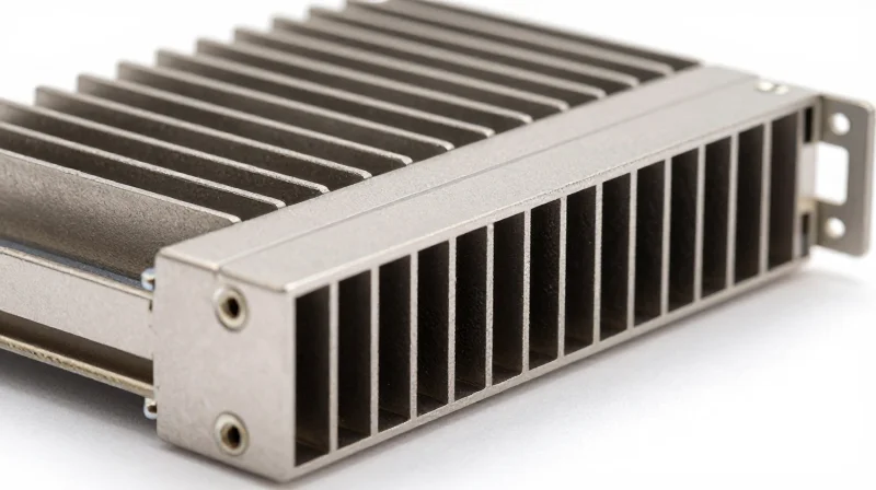
The Octal Small Form-factor Pluggable (OSFP) is the primary physical vehicle for 800G 2xFR4 optics because it resolves the critical thermal bottleneck associated with high-density 112G-per-lane signaling. As power consumption for 800G modules typically ranges between 14W and 18W, the OSFP’s larger physical footprint and integrated cooling fins provide a significant thermal advantage over the competing QSFP-DD standard, ensuring hardware stability and longevity in demanding hyperscale data center environments.
Superior Thermal Architecture: OSFP vs. QSFP-DD
The defining feature of the OSFP form factor is its integrated heatsink. Unlike the QSFP-DD, which relies on a heatsink attached to the cage on the switch motherboard, the OSFP module itself carries the cooling fins. This design allows for direct heat dissipation from the internal optical engines and Digital Signal Processor (DSP) to the airflow stream. Because the 800G 2xFR4 must manage the heat of two 400G engines simultaneously, the OSFP's ability to support a higher power envelope (up to 30W) is a decisive technical benefit.
| Feature | OSFP 800 | QSFP-DD 800 |
|---|---|---|
| Thermal Dissipation | Integrated Module Heatsink | Cage-based System Heatsink |
| Max Power Capacity | Up to 30W | Typically 18W - 20W |
| Module Width | 22.58 mm | 18.35 mm |
| Thermal Resistance | Lower (Superior) | Higher |
Handling the Heat of Dual 400G Engines
The 800G 2xFR4 module effectively houses two complete 400G FR4 optical sub-assemblies (TOSA/ROSA) and a high-performance 7nm or 5nm DSP. This concentrated heat source requires efficient thermal transfer to maintain optimal laser performance. OSFP's 'finned-top' design allows system designers to optimize airflow impedance across the switch chassis, preventing thermal throttling that could otherwise degrade PAM4 signal integrity or lead to a spike in the pre-FEC Bit Error Rate (BER).
- Is OSFP backward compatible with QSFP-DD?
No, they have different physical dimensions and electrical interfaces. However, OSFP-to-QSFP adapters are available for specific port configurations to maintain flexibility in mixed-speed environments. - Why is the integrated heatsink better than a cage-based design?
It reduces the thermal resistance between the heat-generating internal components and the ambient air, allowing for more efficient cooling without requiring the massive increases in fan speed that smaller form factors demand. - Does the OSFP form factor impact port density?
While OSFP modules are slightly wider than QSFP-DD, they are designed to fit 32 ports into a 1U switch front panel, delivering up to 25.6 Tbps of total throughput, matching the density requirements of modern 800G chips.
Connectivity Options: Dual LC vs. MPO Interfaces
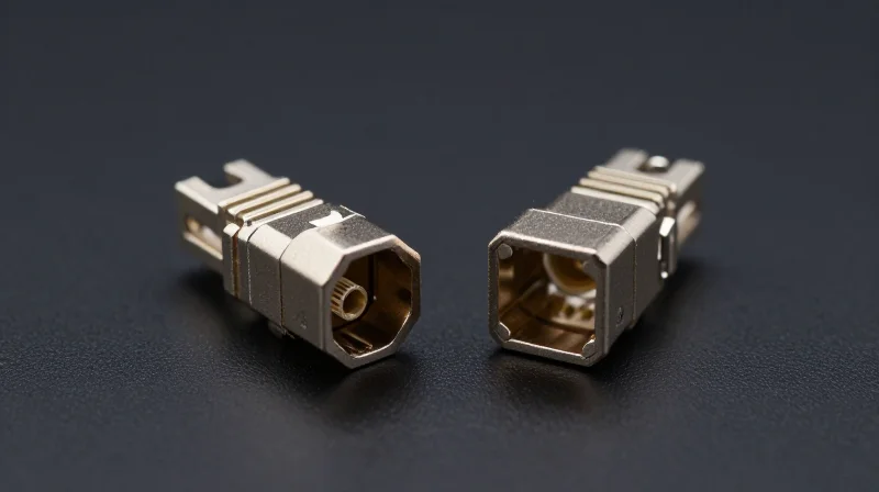
Physical Connectivity and Breakout Flexibility
The 800G OSFP 2xFR4 transceiver is designed to bridge the gap between high-capacity 800G switch ports and standard 400G network infrastructure. Unlike single-port optics, the 2xFR4 leverages its dual-engine architecture to offer two distinct 400G optical channels. This physical layer flexibility is essential for data centers transitioning to 800G, as it allows a single OSFP slot to serve two independent 400G nodes without requiring complex external multiplexing. The choice between Dual LC and MPO interfaces typically depends on existing cable plant density and the specific breakout requirements of the network topology.
Dual Duplex LC Interface: The Standard for Point-to-Point
The most common configuration for the 800G 2xFR4 is the Dual LC interface. This version features two separate LC duplex ports on the transceiver faceplate. Each port represents an independent 400G FR4 engine operating over four CWDM wavelengths. The primary advantage of this design is simplicity; it allows network engineers to use standard, off-the-shelf LC-LC Single Mode Fiber (SMF) patch cords to connect directly to two legacy 400G FR4 modules. This eliminates the cost and cable management overhead associated with specialized breakout cables or patch panels.
MPO-12 Interface: Optimized for High-Density Cabling
For environments utilizing structured cabling or high-density fiber trunks, the MPO-12 (Multi-fiber Push-On) interface is an alternative. In this configuration, both 400G channels are delivered through a single MPO connector. While this reduces the physical footprint on the transceiver faceplate, it necessitates the use of an MPO-to-2xLC breakout cable or an MPO patch panel to split the signals. This setup is often preferred in large-scale spine-and-leaf architectures where fiber management efficiency is prioritized over connector simplicity.
| Feature | Dual Duplex LC Interface | MPO-12 Interface |
|---|---|---|
| Port Configuration | 2 x Discrete Duplex LC Ports | 1 x MPO-12 Port |
| Cable Requirement | Standard Duplex LC SMF | MPO-12 SMF (APC or PC) |
| Breakout Necessity | No external breakout needed | Requires MPO-to-LC breakout |
| Primary Application | Direct server-to-switch or switch-to-switch | Structured cabling and high-density trays |
| Ease of Deployment | High - uses existing standard cables | Moderate - requires specific fiber polarities |
Simplifying Cable Management with Dual-Port Architecture
The transition to 800G often presents a challenge in cable density. The 2xFR4 design solves this by effectively acting as a high-density 400G line card in a small form factor. By utilizing the Dual LC interface, operators can avoid the 'cable spaghetti' often found when using 1-to-8 breakout cables required by DR8 modules. Since the FR4 technology uses WDM to multiplex signals onto a single fiber pair, it significantly reduces the number of required fibers compared to parallel optics, regardless of whether LC or MPO connectors are chosen.
- Can a single 800G 2xFR4 port be used to connect to only one 400G module?
Yes. Because the module consists of two independent engines, one 400G port can be active while the other remains idle, providing a clear migration path for phased network upgrades. - Is the 2xFR4 Dual LC interface compatible with standard 400G FR4 optics?
Absolutely. The optical specifications of each port on the 2xFR4 module are fully compliant with the 400G FR4 standard, ensuring interoperability across different vendor hardware. - What is the maximum reach for these connectivity options?
Both the Dual LC and MPO versions support a transmission distance of up to 2km over Single Mode Fiber, making them ideal for intra-datacenter connections.
Comparative Analysis: 2xFR4 vs. DR8 and FR8
Selecting the Right 800G Interface: 2xFR4, DR8, or FR8?
Choosing between 800G OSFP 2xFR4, DR8, and FR8 depends on three primary factors: the required transmission distance, the existing fiber cabling infrastructure (MPO vs. LC), and the necessity for backward compatibility with 400G systems. The 2xFR4 module is uniquely positioned as a 'dual-engine' solution that bridges the gap between legacy 400G FR4 networks and the next-generation 800G core, offering a 2km reach that DR8 cannot match and a breakout flexibility that standard FR8 lacks.
2xFR4 vs. DR8: Reach and Cabling Density
The 800G DR8 module is designed for short-reach applications, typically up to 500 meters, using parallel single-mode fiber with MPO-12 or MPO-16 connectors. While DR8 is often the most cost-effective solution for intra-rack connections, it requires significantly more fiber strands. The 2xFR4, by contrast, uses CWDM technology to multiplex signals over duplex LC fibers. This allows it to reach up to 2km, making it the superior choice for large-scale data center campuses where fiber conservation and distance are critical.
2xFR4 vs. FR8: Single Pipe vs. Dual Engine
While both 2xFR4 and FR8 support 2km reaches, their internal architectures serve different deployment strategies. The 800G FR8 utilizes eight wavelengths on a single optical path to provide one 800G link. The 2xFR4 uses two sets of four wavelengths (dual 400G engines). This enables the 2xFR4 to act as two independent 400G FR4 ports in a single OSFP slot, providing a seamless breakout path to 400G switches that FR8 cannot easily replicate.
| Feature | 800G DR8 | 800G 2xFR4 | 800G FR8 |
|---|---|---|---|
| Max Reach | 500m | 2km | 2km |
| Optical Connector | MPO-12/MPO-16 | Dual LC | Single LC |
| Fiber Type | Parallel SMF | Duplex SMF | Duplex SMF |
| Main Use Case | Leaf-Spine (Short) | Data Center Interconnect | Core Networking |
Strategic Deployment FAQ
- When is 2xFR4 more cost-effective than DR8?
2xFR4 is more cost-effective when the cost of installing and managing high-count parallel fiber (MPO) exceeds the premium of the WDM components in the 2xFR4 module, particularly for runs between 500m and 2km. - Can 2xFR4 connect directly to 400G FR4 transceivers?
Yes, this is a primary advantage. Because it operates as two independent 400G engines, a 2xFR4 OSFP module can be broken out to two separate 400G FR4 QSFP-DD modules using a simple LC duplex patch cable. - Does 2xFR4 consume more power than FR8?
Generally, 2xFR4 and FR8 have similar power profiles, but the OSFP form factor's integrated heatsink ensures that both can operate efficiently within the 15-18W range required for 800G optics.
Deployment Scenarios: AI Clusters and Spine-Leaf Networking

Deployment Scenarios: AI Clusters and Spine-Leaf Networking
The 800G OSFP 2xFR4 module serves as a critical bridge for high-density AI clusters, providing a seamless path for upgrading data center fabrics from 400G to 800G without a complete overhaul of existing single-mode fiber infrastructure. By integrating two 400G FR4 engines into a single 800G OSFP form factor, this module allows network architects to maximize the bandwidth of 51.2T switches while maintaining backward compatibility with 400G FR4 optical interfaces at the server or leaf layer.
Optimizing AI Backend Fabrics
In AI training environments, GPUs such as the NVIDIA H100 or B200 require massive, non-blocking bandwidth to handle collective communication patterns like All-Reduce. The 2xFR4 design allows a single 800G port on a leaf switch to connect to two separate 400G FR4 ports on AI accelerators or different spine tiers. This breakout capability is essential for scaling backend fabrics where maintaining a 1:1 oversubscription ratio is paramount. The OSFP's integrated heatsink ensures that these modules remain thermally stable even under the persistent, high-load traffic typical of large-scale model training.
| Scenario | Module Benefit | Max Reach |
|---|---|---|
| Spine-to-Leaf Interconnect | High-radix support for massive Clos fabrics | 2km |
| GPU-to-Leaf Breakout | Connects one 800G port to two 400G NICs | 2km |
| Legacy 400G Integration | Interoperates with existing 400G FR4 inventory | 2km |
| Campus Data Centers | Extended reach over standard DR8 options | 2km |
High-Radix Switch Connectivity
Modern 51.2T switches rely on high-radix designs to minimize the number of hops between nodes. Using 800G OSFP 2xFR4 effectively doubles the logical port density of the switch. While a switch may physically have 64 ports of 800G, the 2xFR4 configuration allows it to behave as a 128-port 400G switch. This increased radix is crucial for building large-scale leaf-spine topologies where the number of spine switches often exceeds the physical port count available on standard single-port 800G modules.
- Can 2xFR4 be used to connect to existing 400G FR4 modules?
Yes, the 2xFR4 module is designed specifically to interoperate with two independent 400G FR4 modules using a simple LC-to-LC breakout or patch cable. - Why is 2xFR4 preferred over 2xDR4 in large AI clusters?
While 2xDR4 is limited to 500 meters, 2xFR4 supports distances up to 2km, providing the reach necessary for large-scale campus deployments and complex fiber routing. - Does 2xFR4 require special fiber infrastructure?
No, it utilizes standard G.652 single-mode fiber, making it a cost-effective upgrade for facilities already wired for 100G CWDM4 or 400G FR4.
Future-Proofing Your Network: Migration and Compatibility
Future-proofing a network with 800G OSFP 2xFR4 is achieved by leveraging its dual-engine architecture to maintain seamless interoperability with existing 400G FR4 infrastructure while adopting the OSFP form factor, which is uniquely engineered to handle the thermal demands of next-generation 200G-per-lane signaling.
Seamless Migration via 2x400G Breakout Strategies
The primary migration strategy for 800G OSFP 2xFR4 involves its breakout capability, where a single 800G port can be split into two 400G FR4-compliant links. This allows data center operators to deploy high-radix 800G switches in the spine layer while continuing to use existing 400G leaf switches or network interface cards (NICs). Because the 2xFR4 module uses the same CWDM4 wavelength grid as standard 400G FR4 optics, it requires no changes to the existing duplex single-mode fiber (SMF) plant, significantly reducing capital expenditure during phased upgrades.
| Migration Feature | 400G FR4 Legacy | 800G OSFP 2xFR4 | 1.6T OSFP-XD Path |
|---|---|---|---|
| Electrical Interface | 8x50G or 4x100G PAM4 | 8x100G PAM4 | 8x200G PAM4 |
| Optical Connection | Single LC Duplex | Dual LC Duplex | MPO-16 or Dual LC |
| Fiber Infrastructure | Duplex SMF | Existing Duplex SMF | Parallel or New LC |
| Density Potential | Baseline | 2x 400G Density | 4x 400G Density |
Preparing for the 1.6T Era and 200G SerDes
Deploying 800G OSFP 2xFR4 today prepares the physical infrastructure for the upcoming 1.6T standard. The OSFP form factor's superior heat dissipation capabilities (supporting up to 15W-20W or more) are essential for the transition to 200G per-lane SerDes. As networks scale to 1.6T (8x200G), the investment in OSFP-based hardware ensures that cooling and power delivery systems do not become bottlenecks, allowing for a logical progression to OSFP-XD (Extra Density) modules without a total redesign of the rack thermal management system.
Migration and Compatibility FAQ
- Can I reuse my existing 400G patch panels?
Yes. Since the 800G OSFP 2xFR4 utilizes standard dual-LC connectors, it is fully compatible with the LC-based patch panels and single-mode fiber already used for 400G FR4 deployments. - Is a specialized OSFP cage required for 800G?
Most 800G switches utilize universal OSFP cages that support current 400G and 800G modules and are designed to accommodate the thermal requirements of future 1.6T modules. - Does 2xFR4 support mixed-speed environments?
Absolutely. Through port breakout configuration, a switch can operate certain ports at 800G while others operate as 2x400G, facilitating a heterogeneous network environment during a multi-year migration.
The 800G OSFP 2xFR4 represents a critical milestone in optical engineering, providing the bandwidth necessary for the AI era while maintaining the reliability of established CWDM technology. Selecting the right optics is essential for maximizing network uptime and performance. Ready to upgrade your data center fabric? Contact our technical engineering team for a personalized consultation on 800G deployment strategies.