In the world of high-frequency trading (HFT), the difference between a profit and a loss is often measured in nanoseconds. To stay ahead, financial institutions invest billions in specialized communication pathways known as HFT links. This article provides a comprehensive technical overview of the infrastructure that powers the modern digital gold rush, focusing on the hardware, physics, and protocols that make lightning-fast execution possible.
The Anatomy of a High-Frequency Trading Link
Defining the HFT Link Architecture
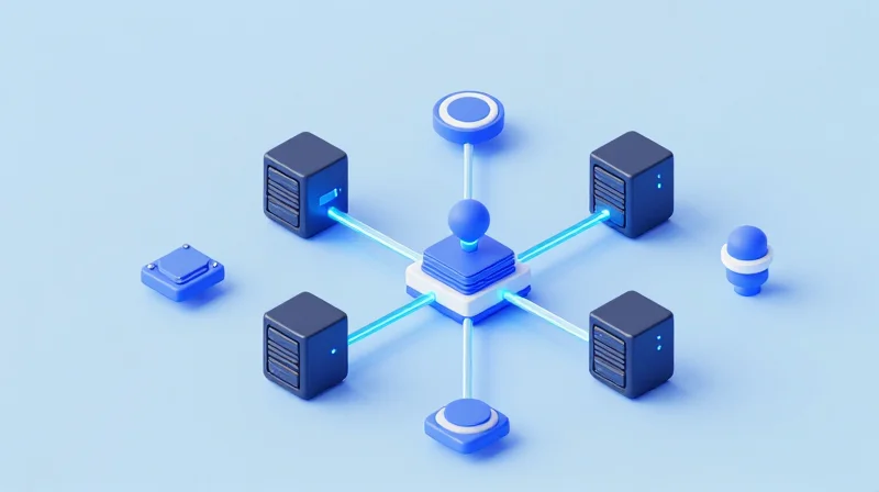
A high-frequency trading (HFT) link is a specialized communication path engineered for the near-instantaneous exchange of financial data between market participants and electronic exchanges. Unlike standard enterprise networks, these links prioritize latency minimization above all other metrics, utilizing a combination of high-grade physical media and hardware-accelerated processing to reduce the 'time-of-flight' for every packet. It serves as the critical nervous system connecting a firm's algorithmic engine to the exchange's matching engine.
The Physical Layer: Path Optimization
The foundation of an HFT link lies in its physical medium. In the world of high-frequency finance, the shortest distance between two points is a 'geodesic' route. Firms invest heavily in dark fiber or wireless technologies to shave nanoseconds off the transmission time. While fiber is the standard for high-bandwidth reliability, wireless microwave and millimeter-wave (mmW) systems are preferred for long-distance inter-city hops because signals travel roughly 30% faster through the air than through silica glass.
| Transmission Medium | Physical Property | Latency Characteristics | Common Usage |
|---|---|---|---|
| Fiber Optics | Refractive Index ~1.5 | Approx. 5 microseconds per km | Market data feeds and intra-city cross-connects |
| Microwave | Refractive Index ~1.0 | Approx. 3.3 microseconds per km | Inter-city routes (e.g., Chicago to New York) |
| Millimeter Wave | High Frequency (30-300GHz) | Ultra-low latency, atmospheric sensitive | Short-range 'last mile' exchange connectivity |
| Hollow-Core Fiber | Air-filled core | Near-vacuum speeds | Emerging tech for localized ultra-low latency |
Hardware Integration and the Logical Layer
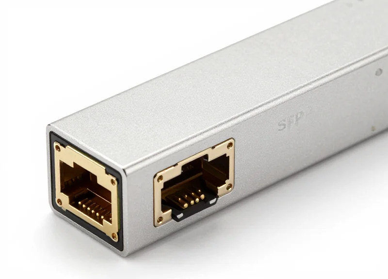
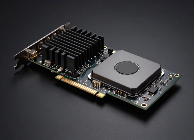
Beyond the cable or wireless dish, the anatomy of an HFT link includes specialized hardware at both ends. Standard Network Interface Cards (NICs) and operating system kernels are bypassed to avoid the 'interrupt' overhead of traditional computing. Instead, Field Programmable Gate Arrays (FPGAs) are used to handle protocol parsing and order generation directly in hardware. This allows the logic layer to process incoming market 'ticks' and emit orders in hundreds of nanoseconds, rather than milliseconds.
- What is 'Tick-to-Trade' latency?
It is the total time elapsed from the moment a market data packet arrives at the HFT link's receiver to the moment the corresponding order packet is transmitted back to the exchange. - Why is 'Jitter' more important than 'Bandwidth'?
In HFT, consistency is key. Jitter (variance in latency) can cause an algorithm to miss a trade window even if the average speed is high; therefore, links are tuned for deterministic performance. - What role do cross-connects play?
A cross-connect is a physical cable within an exchange data center that provides a direct, private link between a trader's server and the exchange's matching engine gateway.
Latency vs. Bandwidth: Prioritizing the Need for Speed
In the world of high-frequency trading (HFT), the 'need for speed' refers specifically to the minimization of round-trip latency—the total time elapsed from the moment an exchange event is triggered to the moment a response is received. While standard enterprise networking often prioritizes bandwidth to move large files or stream video, HFT links are engineered for the lowest possible 'time-to-market.' A microsecond of delay can mean the difference between a profitable execution and a missed opportunity, making bandwidth a secondary concern that is only relevant insofar as it prevents network congestion or packet queuing.
Comparing Latency and Bandwidth in HFT
| Metric | HFT Priority | Standard Networking Priority | Primary Goal |
|---|---|---|---|
| Latency | Critical (Nanoseconds) | Moderate (Milliseconds) | Earliest Arrival |
| Bandwidth | Sufficient (10/25/100 GbE) | Maximum (High Throughput) | Volume Transport |
| Optimization | Straight-line paths / FPGA | Routing / Load Balancing | Speed vs. Capacity |
The Latency Budget: A Micro-Accounting of Time
Network engineers in the HFT space manage a 'latency budget' that accounts for every nanosecond of delay within a trading link. This budget is divided into three primary components: propagation delay, serialization delay, and switching delay. Propagation delay, dictated by the laws of physics, represents the time light or radio waves take to travel through a medium. In vacuum or air, this is roughly 3.3 nanoseconds per meter, whereas in fiber optic cables, it is approximately 5 nanoseconds per meter due to the refractive index of glass.
- 1. Serialization Delay
The time required to push the bits of a packet onto the physical medium. Higher bandwidth links (e.g., 100Gbps) are often used to reduce this specific delay, rather than to increase capacity. - 2. Propagation Delay
The time spent traveling between data centers. This is optimized by utilizing microwave links (which travel through air at nearly the speed of light in a vacuum) instead of underground fiber. - 3. Switching and Logic Delay
The time taken for a network switch or an FPGA-based trading engine to parse headers and make a routing decision. Cut-through switching is mandatory here.
The Role of Bandwidth in Avoiding Congestion
While latency is king, bandwidth cannot be ignored. If the bandwidth of an HFT link is insufficient to handle the burstiness of market data, packets will queue up in the switch buffers. This queuing delay adds unpredictable 'jitter' to the latency budget. Therefore, HFT engineers over-provision bandwidth to ensure that the link remains 'cold' (unused) most of the time, allowing immediate transmission of critical order packets when they are generated.
HFT Infrastructure FAQ
- Why isn't more bandwidth always better?
In HFT, packets are typically very small (e.g., binary market data). Once a link has enough bandwidth to prevent queuing or buffering, additional capacity provides zero benefit to execution speed. - What is the 'Speed of Light' limit?
Nothing travels faster than light in a vacuum. HFT firms spend millions to find the shortest geographic path (geodesic) between two points to stay as close to this physical limit as possible. - How does jitter affect the latency budget?
Jitter is the variance in latency. Even if the average speed is high, high jitter can cause unpredictable execution, which is catastrophic for algorithmic risk management.
Optical Fiber Technologies: From SMF to Hollow Core
Optical Fiber Technologies: From SMF to Hollow Core
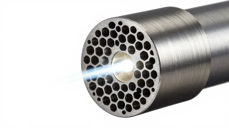
In the world of financial high-frequency trading, the physical medium through which data travels is the ultimate arbiter of speed. While standard Single Mode Fiber (SMF) has been the industry workhorse for decades, its inherent physical property—a solid silica glass core—forces light to travel significantly slower than its theoretical vacuum speed. The emergence of Hollow Core Fiber (HCF) represents a paradigm shift, effectively 'removing' the glass core to allow photons to travel through an air or vacuum medium, thereby slashing the propagation delay by approximately 30%.
Standard Single Mode Fiber (SMF) Limitations
Standard optical fiber, such as SMF-28, relies on a solid glass core with a refractive index of approximately 1.468. According to the formula v = c/n (where c is the speed of light in a vacuum and n is the refractive index), light travels through glass at about 204,190 km/s. For an HFT firm, this translates to a latency of roughly 4.9 microseconds per kilometer. While excellent for general telecommunications, this 'glass ceiling' creates a significant bottleneck when every nanosecond counts.
The Hollow Core Advantage
Hollow Core Fiber (HCF) utilizes complex microstructured internal geometries, such as Photonic Bandgap or Anti-Resonant designs, to guide light through a central hole filled with air or vacuum. Since air has a refractive index of nearly 1.0, light travels at approximately 299,700 km/s. This reduction in the refractive index allows for a propagation speed that is nearly 99.7% of the speed of light in a vacuum, providing a massive competitive advantage over competitors still using solid-core glass.
| Metric | Single Mode Fiber (SMF) | Hollow Core Fiber (HCF) |
|---|---|---|
| Core Material | Solid Silica Glass | Air / Vacuum |
| Refractive Index (n) | ~1.468 | ~1.0003 |
| Speed of Light | ~68% of c | ~99.7% of c |
| Latency (per km) | ~4.90 μs | ~3.34 μs |
| Latency Saving | Baseline | ~1.56 μs per km |
Engineering Constraints and Practical Deployment
- Why isn't all fiber Hollow Core?
HCF is significantly more expensive to manufacture and has historically suffered from higher signal attenuation (loss) compared to SMF, making it suitable mostly for short-to-medium distance metro links rather than transoceanic spans. - Is HCF compatible with standard hardware?
While the light remains within the IR spectrum, HCF requires specialized fusion splicing techniques to connect to standard SMF equipment without collapsing the air-filled microstructures. - What is the primary HFT use case?
HCF is predominantly used for the 'last mile' or 'golden path' between a proprietary trading server and the exchange's matching engine gateway within a data center campus.
The Role of DWDM in Financial Connectivity

The Role of DWDM in Financial Connectivity
Dense Wavelength Division Multiplexing (DWDM) is a critical physical layer technology that allows HFT firms to maximize the utility of their expensive fiber-optic assets by transmitting multiple independent data streams simultaneously over a single fiber pair. By using different wavelengths—or colors—of light for each stream, DWDM effectively turns a single physical path into dozens of virtual high-speed highways. Crucially for financial markets, this process occurs at the optical layer (Layer 1), which bypasses the store-and-forward delays inherent in traditional Layer 2/3 networking equipment, ensuring that the 'speed-of-light' propagation remains unhindered by electronic processing overhead.
Eliminating the Packet Processing Tax
In a standard network environment, increasing bandwidth usually involves adding switches and routers that must inspect every packet header to determine its destination. In HFT links, this 'packet processing tax' is unacceptable. DWDM utilizes passive and active optical components like multiplexers (MUX) and demultiplexers (DEMUX) to combine and separate signals based purely on their frequency. Because these devices do not look at the data payload or the protocol headers, the latency added is measured in mere nanoseconds—largely the result of the light traveling through the internal glass of the DWDM hardware itself.
| Feature | Standard Packet Switching | DWDM Optical Layer |
|---|---|---|
| Primary Metric | Throughput/Bandwidth | Propagation Latency |
| Processing Type | Electronic (Store-and-Forward) | Optical (Wavelength Multiplexing) |
| Added Latency | Microseconds (Variable) | Nanoseconds (Deterministic) |
| Scalability | Requires new hardware/cables | Requires new wavelength assignments |
Multi-Stream Efficiency and Protocol Transparency
One of the primary advantages of DWDM in HFT is protocol transparency. A single fiber can carry a 10GbE market data feed on one wavelength, a 40GbE order execution path on another, and a proprietary synchronization signal on a third. This allows firms to consolidate diverse traffic types without interference. Furthermore, since each wavelength is physically isolated from the others, there is no 'head-of-line blocking' where a large burst of market data might delay a critical trade execution signal.
Technical FAQ: DWDM in Low-Latency Environments
- Does DWDM amplification add latency?
Yes, Erbium-Doped Fiber Amplifiers (EDFAs) used in long-haul DWDM links add several meters of fiber spooling inside the device, which adds a small but fixed amount of latency. However, for short-haul metro links typical in HFT, passive DWDM is often used to avoid this delay entirely. - How does Chromatic Dispersion affect HFT links?
Chromatic Dispersion causes light pulses to spread out as they travel, which can lead to data errors at high speeds. While dispersion compensation modules can fix this, they add significant latency. HFT engineers often prefer using dispersion-shifted fiber or specific laser types to minimize the need for compensation. - What is the advantage of 'Thin' DWDM?
Thin or Passive DWDM configurations eliminate active electronics between the transceivers. This reduces power consumption, lowers the probability of hardware failure, and ensures the absolute minimum physical path length between the exchange and the trading engine.
Microwave and Millimeter Wave: Cutting Through the Air
Microwave and Millimeter Wave: Cutting Through the Air
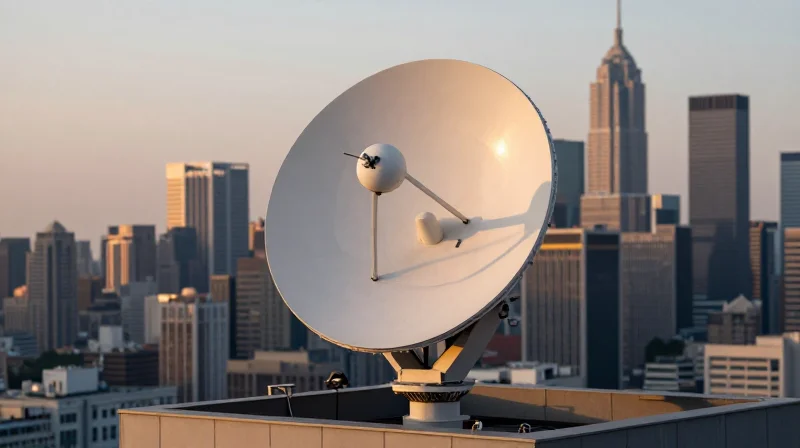
In the pursuit of the lowest possible latency, terrestrial microwave and millimeter-wave (mmWave) links represent the gold standard for long-distance connectivity between financial hubs. Unlike optical fiber, which transmits light through a glass medium that slows signals to approximately 200,000 km/s, microwave signals travel through the atmosphere at nearly the speed of light in a vacuum. This physical advantage, combined with the ability to traverse a straight-line 'as the crow flies' path rather than following convoluted subterranean infrastructure, allows microwave networks to achieve latencies that fiber-optic systems physically cannot match.
The Physics of Propagation: Velocity and Path Efficiency
The technical edge of wireless links is rooted in the refractive index. Standard silica fiber has a refractive index of roughly 1.47, meaning light travels about 31% slower than its theoretical maximum. Atmospheric air has a refractive index of approximately 1.0003, offering virtually no resistance to signal velocity. For a critical route like the 1,180 km path between Chicago and New Jersey, this difference translates to a round-trip time (RTT) reduction of approximately 2 milliseconds—a massive competitive advantage in HFT.
| Metric | Fiber Optic (SMF) | Microwave (Terrestrial) |
|---|---|---|
| Propagation Velocity | ~0.67c | ~0.99c |
| Transmission Medium | Silica Glass | Free Space (Air) |
| Path Geometry | Follows Utility Easements | Direct Geodesic Path |
| Latency (Chicago-NY) | ~13.0ms - 14.5ms | ~8.5ms - 9.0ms |
| Reliability | High (99.999%) | Variable (Weather Dependent) |
Spectrum Selection and the Rain Fade Challenge
HFT firms typically utilize frequency bands ranging from 6 GHz to 80 GHz (E-band). Lower frequencies offer better range and penetration through rain but provide less bandwidth. Higher millimeter-wave frequencies allow for massive data throughput but are susceptible to atmospheric attenuation and 'rain fade,' where water droplets absorb signal energy. To counter this, engineers design networks with high-gain parabolic antennas and utilize Adaptive Modulation (ACM) to maintain connectivity during storms, albeit at reduced bitrates.
latency_fiber = (distance * 1.47) / 299792458
latency_air = (distance * 1.0003) / 299792458- Why is microwave faster than fiber if light speed is constant?
While the speed of light in a vacuum is constant, it slows down when passing through materials. Glass fiber acts as a 'slower' medium than air, and physical fiber cables rarely follow the perfectly straight line that a wireless microwave beam can achieve between towers. - What happens to HFT trades when it rains?
When heavy rain or snow attenuates the microwave signal beyond the 'fade margin,' the network may experience packet loss or a total outage. Most HFT firms use 'hybrid' routes where the system automatically fails back to a fiber-optic link if the wireless signal quality drops below a specific threshold. - What is a Fresnel Zone in HFT microwave links?
The Fresnel Zone is an elliptical region around the line-of-sight path. HFT engineers must ensure this zone is clear of buildings or trees, as obstructions within it can cause signal interference and phase shifts that increase jitter and latency.
Switching and Routing: FPGA and Layer 1 Technologies
In the world of high-frequency trading (HFT), the millisecond is an eternity, and the microsecond is the standard unit of competition. Achieving sub-microsecond latency requires a fundamental shift away from general-purpose CPUs and traditional networking stacks. By utilizing Field Programmable Gate Arrays (FPGAs) and Layer 1 (L1) switches, firms can process market data and execute trades directly in hardware circuitry. This approach bypasses the Linux kernel, interrupts, and memory-copy operations that characterize standard networking, allowing for deterministic, ultra-low latency execution.
Layer 1 Switching: The Virtual Patch Panel
Traditional Layer 2 or Layer 3 switches operate on a 'store-and-forward' or 'cut-through' basis, where they must examine packet headers to make forwarding decisions. This process adds hundreds of nanoseconds to the path. In contrast, Layer 1 switches act as an electronic matrix or 'crosspoint' switch. They function as a programmable patch panel, electrically mapping one port to another with almost no logic processing.
| Switch Type | Typical Latency | Primary Function | Methodology |
|---|---|---|---|
| Layer 3 Router | 5 μs - 50 μs | IP-based routing | Software/ASIC routing tables |
| Layer 2 Switch | 200 ns - 2 μs | MAC-based forwarding | Cut-through or Store-and-forward |
| Layer 1 Switch | 4 ns - 10 ns | Physical replication | Crosspoint matrix/Signal regeneration |
FPGA: Custom Silicon for Trading Logic
While Layer 1 switches handle the transport, FPGAs handle the intelligence. An FPGA is a piece of hardware that can be programmed using Hardware Description Languages (HDL) like Verilog or VHDL to perform specific tasks. In HFT, FPGAs are often embedded directly into the Network Interface Card (NIC). This allows the hardware to parse incoming market data packets (e.g., NASDAQ ITCH or NYSE Pillar) and trigger a buy/sell order in as little as 10 to 50 nanoseconds, far faster than any C++ or Java application running on a standard CPU.
The Importance of Determinism and Jitter
Beyond raw speed, the primary advantage of FPGA and Layer 1 technology is determinism. General-purpose operating systems suffer from 'jitter' caused by CPU scheduling, cache misses, and background system tasks. Hardware-based logic ensures that every packet is processed in the exact same number of clock cycles, every single time. This predictability is vital for risk management and strategy backtesting in competitive electronic markets.
- What is Kernel Bypass?
Kernel bypass is a technique that allows an application to send and receive data directly from the network hardware, avoiding the Linux kernel's networking stack to reduce latency and CPU overhead. - Why can't standard CPUs match FPGA speeds?
CPUs follow a sequential fetch-decode-execute cycle and rely on complex branch prediction. FPGAs process data in parallel using dedicated logic gates, meaning they can perform multiple operations simultaneously in a single clock cycle. - Is FPGA programming harder than traditional software?
Yes, FPGA development requires thinking in terms of hardware gates and timing constraints rather than sequential instructions, making the development cycle much longer and more complex than standard software engineering.
Path Optimization and Geodesic Routes
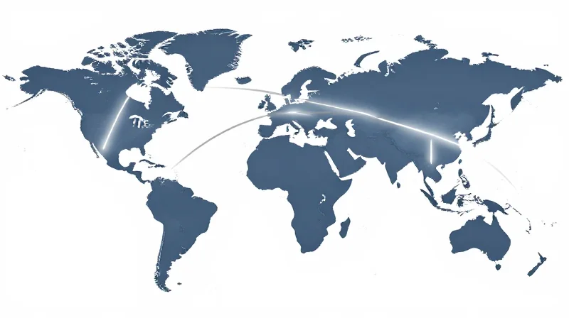
In the realm of high-frequency trading (HFT), the physical distance between two trading hubs is the ultimate arbiter of latency. Because signal velocity is strictly limited by the speed of light, the only remaining variable for engineers to manipulate is the length of the path itself. By establishing routes that adhere as closely as possible to a geodesic—the shortest distance between two points on a sphere—firms can achieve the 'theoretical minimum' latency required to remain competitive in global markets.
The Geodesic Imperative: Minimizing Physical Distance
The pursuit of the 'Great Circle' route has led to massive infrastructure investments, such as the famous Project Spread, which involved drilling through the Allegheny Mountains to create a straighter fiber path between Chicago and New York. While traditional telecommunications infrastructure follows existing rights-of-way like highways and railways, HFT-specific links are designed to ignore these constraints, often cutting across private land to shave a few kilometers—and thus several microseconds—off the signal's journey.
| Route Type | Medium | Approx. Latency (NJ to Chicago) | Path Efficiency |
|---|---|---|---|
| Legacy Fiber | Silica Glass | ~14-16ms | Low (Follows public roads) |
| Optimized Fiber | Silica Glass | ~13.1ms | Medium (Direct private path) |
| Microwave Link | Air | ~8.5-9.0ms | High (Near-Geodesic) |
| Theoretical Limit | Vacuum | ~7.9ms | Perfect (True Geodesic) |
The Speed of Light in Media: Fiber vs. Air
Path optimization is not solely about the geometry of the route; it also accounts for the refractive index of the medium. Light travels at approximately 299,792 kilometers per second in a vacuum, but its speed drops by about 31% when passing through the silica glass used in fiber optic cables. Terrestrial microwave and millimeter-wave links provide a dual advantage: they allow for straighter 'line-of-sight' paths between towers and they propagate signals through the air, where the refractive index is nearly 1.0, allowing signals to travel at roughly 99.97% of the speed of light in a vacuum.
- Why can't fiber links achieve the same speed as microwave?
Even if a fiber path is perfectly straight, the light is slowed down by the glass medium itself, whereas microwave signals travel through the atmosphere at near-vacuum speeds. - What is 'shaving' in path optimization?
Shaving refers to the process of identifying minor bends or detours in a network route and replacing them with shorter segments to reduce latency by nanoseconds. - How do topographical barriers affect geodesic routes?
Mountains, water bodies, and urban density force deviations from the geodesic. HFT firms overcome this by using high-altitude microwave relays or drilling tunnels for fiber.
Challenges in Maintaining Direct-Path Links
Maintaining a geodesic microwave link requires a chain of line-of-sight towers, each perfectly aligned. Atmospheric conditions, such as heavy rain (rain fade) or thermal inversion, can disrupt these paths, forcing HFT firms to maintain 'failover' fiber routes. These fiber backups are also optimized for distance but serve as a more stable, albeit slower, secondary path when the primary 'straight-line' wireless link is compromised.
Network Monitoring and Determinism
The Critical Role of Determinism and Jitter Mitigation
In the world of high-frequency trading (HFT), raw speed is only half of the equation; the other half is determinism. Determinism refers to the predictability of the network's performance, ensuring that every packet traverses the link in a consistent timeframe. Jitter—the variance in latency between packets—is often more damaging than a slightly higher constant latency. When a network exhibits high jitter, a trading algorithm cannot accurately predict its position in the exchange matching engine's queue, leading to 'missed' trades or 'toxic' fills where the market has already moved against the position before the order arrives. Achieving determinism requires a radical simplification of the network stack, removing any variable-delay components such as OS-level interrupts or complex routing protocols.
| Metric | Definition | Impact on HFT |
|---|---|---|
| Latency | The total time elapsed for a packet to travel from source to destination. | Determines the absolute speed limit and competitive edge for execution. |
| Jitter | The statistical variation in the delay of received packets over time. | Destroys strategy synchronization and leads to unpredictable queue priority. |
| Micro-bursting | Sudden, millisecond-scale spikes in traffic volume. | Causes buffer overflows and non-deterministic queuing delays in legacy switches. |
Monitoring Infrastructure: TAPs and Hardware Timestamping
To maintain a deterministic environment, firms use passive Network TAPs (Test Access Points) rather than traditional SPAN ports. SPAN ports are managed by the switch's CPU and can drop packets or introduce variable delays under heavy load, making them useless for HFT diagnostics. In contrast, passive TAPs provide a bit-for-bit copy of the data stream with zero impact on the production path. These mirrored streams are fed into dedicated capture appliances equipped with FPGA-based NICs that apply hardware-level timestamps. By leveraging the Precision Time Protocol (PTP) IEEE 1588v2, firms can synchronize clocks across disparate global data centers with sub-microsecond precision, allowing for 'one-way' latency measurements that reveal exactly where a micro-burst or bottleneck is occurring.
Ensuring Performance Consistency
- How does PTP differ from NTP in HFT?
While NTP provides millisecond accuracy suitable for general logs, PTP (Precision Time Protocol) utilizes hardware-level timestamping to achieve nanosecond-level synchronization required for high-speed trade correlation. - Why is 'First-In, First-Out' (FIFO) critical for determinism?
HFT firms optimize for FIFO at every layer to ensure that the order of packet arrival is strictly preserved, preventing 'out-of-order' delivery that would force the application to wait and introduce jitter. - What is the impact of bufferbloat on trading links?
Bufferbloat occurs when network equipment holds too much data in buffers during congestion, causing high latency; HFT networks use ultra-shallow buffers or 'bufferless' designs to drop stale packets rather than delay them.
Ultimately, the goal of monitoring in a high-frequency environment is not just to see that the network is 'up,' but to prove that it is performing exactly the same way for every single packet. In a race measured in nanoseconds, any deviation from the baseline is a signal of a systemic failure that must be engineered out of the path.
The Future of HFT Connectivity: Quantum and LEO Satellites
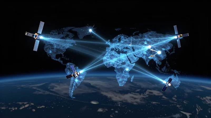
The future of financial high-frequency trading links lies in bypassing the physical limitations of terrestrial fiber-optics through vacuum-based signal propagation via Low Earth Orbit (LEO) satellite constellations and ensuring absolute data integrity using Quantum Key Distribution (QKD). As traditional microwave and millimeter-wave networks reach their theoretical limits on land, the focus is shifting to the 'straightest' path possible: the vacuum of space, where light travels approximately 30% to 47% faster than it does through the glass cores of fiber-optic cables.
LEO Satellites: The Ultimate Geodesic Path
While terrestrial microwave towers are limited by geography and the Earth's curvature, LEO satellites (operating at altitudes of 550km to 1,200km) create a direct line-of-sight network across oceans and continents. For HFT firms engaged in cross-continental arbitrage—such as London to Tokyo or New York to Singapore—the latency reduction is revolutionary. Unlike traditional geostationary satellites that introduce massive lag due to their distance (35,000km+), LEO constellations like SpaceX's Starlink or Amazon's Kuiper offer a path where the signal moves through a vacuum, significantly outperforming subsea fiber cables that must snake around tectonic plates and continental shelves.
| Transmission Medium | Signal Velocity (Approx.) | Latency Advantage | Primary Constraint |
|---|---|---|---|
| Terrestrial Fiber | ~200,000 km/s | Baseline | Refractive index of glass; physical path zig-zags |
| Microwave (Air) | ~299,700 km/s | ~33% faster than fiber | Atmospheric interference; geographic obstacles |
| LEO Satellites (Vacuum) | ~299,792 km/s | ~47% faster than fiber | Orbital mechanics; high CAPEX; signal 'hand-offs' |
Quantum Communication and Synchronization
Beyond pure speed, the 'Quality of Link' in HFT is becoming increasingly dependent on Quantum Key Distribution (QKD) and ultra-precise time synchronization. Quantum networking offers a method for HFT firms to secure their proprietary trade signals with 'unbreakable' encryption, where any attempt to intercept the packet collapses the quantum state, immediately alerting the firm to a breach. Furthermore, quantum entanglement is being researched as a means to achieve near-instantaneous clock synchronization between disparate trading servers, reducing the 'jitter' caused by PTP (Precision Time Protocol) drift over long distances.
Challenges and FAQs in Next-Gen Connectivity
- Will LEO satellites replace microwave towers?
Unlikely. Microwave remains superior for short-distance, intra-city links (e.g., New Jersey to Chicago) due to lower equipment complexity and atmospheric overhead. Satellites are the gold standard for trans-oceanic and global arbitrage. - What is the biggest technical hurdle for satellite HFT?
Atmospheric scintillation and 'weather fading.' Heavy rain or solar activity can degrade signal-to-noise ratios, leading to packet loss that HFT systems cannot tolerate, necessitating hybrid systems with fiber backups. - Is 'Quantum Entanglement' used for data transmission?
No. Quantum entanglement cannot transmit information faster than the speed of light (due to the No-Communication Theorem), but it is used for highly secure key generation and hyper-accurate clock synchronization.
As financial markets become increasingly automated, the technical sophistication of HFT links remains the ultimate competitive differentiator. From Hollow Core Fiber to FPGA integration, optimizing every inch of the network is essential. If you are looking to upgrade your financial network infrastructure to achieve world-class latency benchmarks, contact our engineering team for a consultation today.