In the rapidly evolving landscape of telecommunications, the demand for specialized, high-performance optical hardware is at an all-time high. Understanding the nuances between OEM and ODM services is critical for businesses looking to scale their network infrastructure with precision-engineered components. This guide provides a deep dive into the technical frameworks and strategic decision-making involved in custom optical manufacturing.
Defining OEM vs. ODM in the Optical Industry
Defining OEM vs. ODM in the Optical Industry
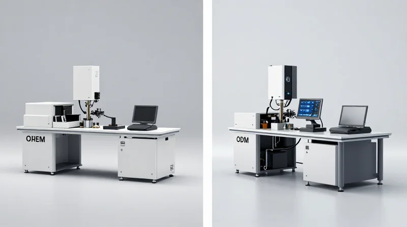
In the context of optical manufacturing, the distinction between OEM (Original Equipment Manufacturing) and ODM (Original Design Manufacturing) is primarily defined by which party provides the technical design and holds the intellectual property (IP). OEM services involve a client providing full engineering blueprints and specifications for a manufacturer to execute—essentially 'build-to-print'—whereas ODM services involve the manufacturer designing and producing a product based on a general functional requirement provided by the client, often referred to as 'white-labeling' or 'private labeling' with technical customization.
The OEM Path: Precision Execution of Proprietary Designs
Original Equipment Manufacturing is the preferred route for companies with robust internal R&D departments. In photonics, this might involve a company designing a unique laser diode housing or a proprietary fiber optic sensor array. The OEM partner provides the specialized cleanroom environments, automated alignment systems, and assembly expertise required to bring that specific design to life without altering the optical physics or mechanical constraints established by the client. The client retains full control over the Bill of Materials (BOM) and manufacturing process standards.
The ODM Path: Leveraging Manufacturer Expertise
Original Design Manufacturing is a strategic choice for companies looking to expand their product catalog quickly without heavy investment in optical engineering. An ODM in the fiber optics space often has a portfolio of 'base' designs for common components like optical transceivers, splitters, or amplifiers. A client can select a base model and request minor modifications—such as specific connector types, casing branding, or firmware adjustments. The manufacturer maintains the core IP of the design, allowing for lower upfront Non-Recurring Engineering (NRE) costs and a faster path to market.
| Feature | OEM (Original Equipment Manufacturing) | ODM (Original Design Manufacturing) |
|---|---|---|
| Design Ownership | Client-owned IP | Manufacturer-owned IP |
| R&D Responsibility | Client engineers the product | Manufacturer engineers the product |
| Customization Level | Absolute; dictated by blueprints | Limited to existing design platforms |
| Cost Profile | High initial NRE; lower per-unit cost | Low initial NRE; higher per-unit margin |
| Market Speed | Slower (due to development cycle) | Rapid (utilizing existing designs) |
Key Technical Differentiators
- Who controls the Optical Design?
In OEM, the client specifies the exact glass types, coating specifications, and tolerances. In ODM, the manufacturer selects the optical components that best meet the performance targets requested. - When should a firm choose OEM?
OEM is ideal for breakthrough technologies where the optical design is a competitive advantage that must be kept strictly confidential and proprietary. - When should a firm choose ODM?
ODM is best for standardized optical hardware where the value-add is in the software, branding, or distribution rather than the fundamental hardware design.
Core Hardware Spectrum: From Transceivers to Passive Components
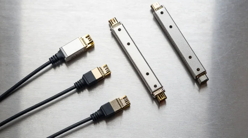
The hardware spectrum for optical OEM/ODM services is divided into active and passive categories, encompassing everything from sophisticated 800G transceivers and EDFA amplifiers to foundational elements such as PLC splitters and wavelength-division multiplexing (WDM) filters. While OEM services typically focus on high-volume production of standardized blueprints, ODM services allow for deep technical customization of these components to meet specific link budgets, environmental tolerances, or proprietary form factors.
Active Components: High-Speed Modules and Amplification
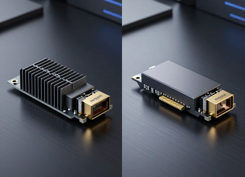
Active components represent the most complex segment of optical manufacturing, requiring rigorous testing for signal integrity and thermal management. OEM/ODM providers specialize in the assembly of high-speed transceivers including QSFP28, QSFP-DD, and OSFP form factors. Beyond simple assembly, ODM services for active components often involve optimizing the Firmware (FW) or the Microcontroller Unit (MCU) code to ensure interoperability with specific switch architectures from major vendors.
| Component Category | Typical OEM Scope | Typical ODM Scope |
|---|---|---|
| Active Transceivers | Standard 100G/400G/800G production. | Custom EEPROM programming & PCB layout optimization. |
| Optical Amplifiers | Fixed-gain EDFA assembly. | Variable gain/tilt control and custom housing for outdoor use. |
| Active Optical Cables | Mass production of standard lengths. | Hardened jacketing and low-power silicon photonics integration. |
Passive Components: Precision and Scalability
Passive components are the silent workhorses of the network, requiring extreme precision in glass processing and packaging. Planar Lightwave Circuit (PLC) splitters and Thin Film Filter (TFF) based WDM modules are frequently produced via OEM models to reduce costs. However, ODM services become vital when designing specialized Mux/Demux solutions that require non-standard channel spacing or integrated monitoring ports for fiber-tapping applications.
Commonly Outsourced Hardware Capabilities
- What speeds are supported in OEM transceiver manufacturing?
Current OEM capabilities scale from 10G SFP+ up to 800G OSFP/QSFP-DD, utilizing both EML and Silicon Photonics platforms. - Can ODM services customize WDM filter wavelengths?
Yes, ODM providers can engineer custom CWDM, DWDM, and LWDM grids, including O-band and C-band specifications for 5G fronthaul or DCI applications. - Are EDFA amplifiers available for custom form factors?
ODM services allow for the miniaturization of EDFA modules into 'Gain Block' formats or integration into pluggable MSA housings.
Selecting the right point on this hardware spectrum depends on the project's maturity; high-volume, established tech benefits from the efficiency of OEM, while emerging or niche hardware requirements necessitate the engineering depth of an ODM partnership.
Technical Standards and MSA Compliance
The Critical Role of Technical Standards in Optical Manufacturing
Technical standards in the optical industry are not merely suggestions; they are the fundamental blueprints that allow OEM and ODM partners to produce hardware that is globally compatible. For a service provider or data center operator, these standards—primarily Multi-Source Agreements (MSA) and IEEE 802.3 specifications—ensure that a transceiver manufactured by an ODM in one region will perform predictably when plugged into a switch developed by an OEM in another. This interoperability is what prevents vendor lock-in and drives down costs through healthy market competition by ensuring that the 'plug-and-play' nature of fiber optics remains intact across different brands.
Understanding Multi-Source Agreements (MSA)
MSAs are industry-led agreements between manufacturers to define the form factor and interface of optical modules. While not official standards bodies like the ISO or IEEE, MSAs dictate the physical dimensions (mechanical footprint), the electrical interface (pin mapping), and the management interface (EEPROM memory maps) used for digital diagnostics monitoring (DDM). In the context of OEM/ODM, the MSA is the technical contract that ensures a custom-designed module will physically fit and electrically communicate with the host system.
| Feature | MSA (Multi-Source Agreement) | IEEE (e.g., 802.3) |
|---|---|---|
| Primary Focus | Mechanical and Electrical Interface | Data Transmission and Protocol |
| Physical Definition | Defines dimensions (SFP, QSFP-DD, OSFP) | Agnostic to the physical module shape |
| Signal Logic | Defines I2C registers and DDM data | Defines modulation (NRZ, PAM4) and BER |
| Interoperability | Ensures the module fits the switch port | Ensures the light signal reaches the far end |
IEEE Compliance and Performance Benchmarks
While the MSA governs how a module looks and talks to the switch, IEEE standards govern how the module sends light through the fiber. For an ODM project, adhering to IEEE 802.3 standards (such as 802.3bm for 100G or 802.3bs for 400G) is non-negotiable. These standards define the Bit Error Rate (BER), optical power levels, and wavelength tolerances. During the OEM/ODM validation phase, engineers use high-end oscilloscopes to perform 'Eye Diagram' analysis, ensuring the signal quality meets these strict IEEE thresholds to prevent data loss over long distances.
Common Questions on Standards and Compliance
- Can an ODM module work in any brand's switch?
Yes, provided the module is MSA-compliant. However, some OEMs implement software 'vendor locks' that require the ODM to program specific firmware codes into the module's EEPROM to ensure compatibility. - Why is 'EEPROM Coding' part of MSA compliance?
The MSA defines the memory map (SFF-8472 or SFF-8636). ODM services often include 'custom coding' where the manufacturer writes specific serial numbers and vendor IDs into this memory so the host hardware recognizes the component. - What happens if a product is not IEEE compliant?
Non-compliance typically results in high packet loss, reduced transmission distance, or total link failure when connecting to equipment from other compliant manufacturers.
The Engineering Workflow: From Schematic Design to Prototyping
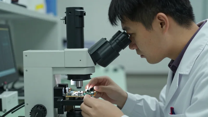
The engineering workflow in optical OEM/ODM is a multi-disciplinary approach that transforms a functional specification into a manufacturable reality by balancing optical precision with electrical performance. For high-speed interconnects like 800G transceivers, the transition from schematic design to physical prototyping is governed by strict signal integrity (SI) requirements and thermal envelopes defined by Multi-Source Agreements (MSAs), ensuring that the final hardware can operate reliably within high-density data center environments.
Signal Integrity (SI) and PCB Layout for High-Frequency Optics
As data rates migrate toward 112G and 224G SerDes, the PCB layout becomes a primary constraint rather than a secondary consideration. Engineers must utilize advanced CAD tools to manage trace geometry, minimize via stubs, and select appropriate dielectric materials to mitigate jitter and Bit Error Rate (BER). Differential pair routing is executed with extreme precision to account for intra-pair skew and electromagnetic coupling, often necessitating 'back-drilling' of vias to eliminate resonant stubs that would otherwise disrupt high-frequency signal paths.
| Design Challenge | Engineering Strategy | Impact on Performance |
|---|---|---|
| Impedance Discontinuity | TDR analysis and controlled trace geometry | Reduces signal reflections and return loss |
| Electromagnetic Interference (EMI) | Integrated shielding and multi-layer ground planes | Prevents crosstalk between high-speed lanes |
| High Insertion Loss | Low-loss PTFE or high-Tg materials | Extends reach and maintains signal amplitude |
Thermal Management and CFD Simulation
With modern 800G OSFP modules consuming up to 18W, thermal dissipation is a critical engineering bottleneck. The workflow involves rigorous Computational Fluid Dynamics (CFD) simulations to optimize heat sink fin density and the placement of Thermal Interface Materials (TIMs). ODM providers develop custom integrated heat spreaders and conduct thermal cycling tests to ensure that internal TOSA/ROSA components remain within their optimal operating temperature range, preventing wavelength drift and premature component failure.
Prototyping Milestones: EVT to PVT
- Engineering Validation Test (EVT)
The first physical build focused on core functionality, electrical bring-up, and initial firmware debugging. - Design Validation Test (DVT)
Testing the hardware against environmental extremes, MSA compliance, and long-term reliability (MTBF). - Production Validation Test (PVT)
The final pilot run using mass-production tooling to ensure the manufacturing process is repeatable and efficient.
Engineering Workflow FAQs
- How is Signal Integrity validated before a prototype is built?
Engineers utilize 3D electromagnetic field solvers (such as Ansys HFSS) to model the entire channel, generating S-parameter files and eye diagrams to predict performance. - What role does the 'Golden Sample' play in the ODM process?
A Golden Sample serves as the performance benchmark for all subsequent units, used to calibrate automated test equipment (ATE) on the production line. - Why are multi-layer PCBs (14+ layers) common in optical design?
High layer counts allow for dedicated ground and power planes, which provide the isolation and stable reference required for high-frequency signal paths.
Advanced Customization for 400G and 800G Networks

Advanced customization for 400G and 800G networks represents a paradigm shift where ODM providers move beyond simple hardware assembly to become deep-tech engineering partners. As data rates climb, the physical limitations of copper and traditional laser packaging necessitate bespoke solutions in Digital Signal Processing (DSP) tuning, silicon photonics integration, and high-density form factors like QSFP-DD and OSFP. Success in this tier requires a focus on reducing Bit Error Rates (BER) while managing the exponential increase in thermal output generated by high-velocity PAM4 signaling.
The Transition to PAM4 and DSP Optimization
Unlike the NRZ (Non-Return to Zero) modulation used in 100G, 400G and 800G utilize 4-level Pulse Amplitude Modulation (PAM4). This doubles the data rate within the same bandwidth but significantly reduces the Signal-to-Noise Ratio (SNR). ODM services provide critical value here by customizing the DSP firmware to implement advanced Forward Error Correction (FEC) algorithms. This ensures that the transceiver can recover signals effectively across varying fiber lengths and link budgets, specifically tailored to the client's proprietary switch environment.
Comparing 400G and 800G Engineering Specifications
| Parameter | 400G Requirements | 800G Requirements |
|---|---|---|
| Modulation | 56G PAM4 | 112G PAM4 |
| Typical Form Factors | QSFP-DD / OSFP | OSFP800 / QSFP-DD800 |
| Power Consumption | 10W - 14W | 16W - 24W |
| Optical Components | EML / SiPh | Thin-Film LNOI / SiPh |
| Testing Focus | TDECQ Compliance | Lane-to-Lane Skew / Jitter |
Silicon Photonics and Co-Packaged Optics (CPO)
To combat power density issues, ODMs are increasingly leveraging silicon photonics (SiPh). By integrating optical and electronic components on a single CMOS-compatible silicon chip, providers can reduce the component count and lower power consumption per bit. For 800G and the upcoming 1.6T era, ODM customization often involves Co-Packaged Optics (CPO) development, where the optical engine is moved closer to the switch ASIC to minimize electrical trace loss and significantly improve energy efficiency in hyper-scale data centers.
Thermal Management Solutions for High-Density Pluggables
Thermal dissipation is the primary bottleneck for 800G OSFP/QSFP-DD modules. Custom ODM services include the design of advanced heat sinks and the selection of high-conductivity Thermal Interface Materials (TIM). Engineering workflows focus on computational fluid dynamics (CFD) simulations to ensure that the transceiver remains within operational temperature ranges (usually 0°C to 70°C for commercial grade) even when fully loaded in a high-density 32-port or 64-port switch chassis.
- How does ODM customization improve 800G interoperability?
ODMs conduct extensive 'golden unit' testing against various switch vendors (Cisco, Arista, Juniper) to ensure the CMIS (Common Management Interface Specification) is perfectly tuned for the host system's polling logic. - What role does EML vs. Silicon Photonics play in 800G ODM?
Electro-absorption Modulated Lasers (EML) offer higher performance for long-reach (LR) applications, whereas Silicon Photonics are favored for short-reach (DR/FR) high-volume deployments due to lower cost and power efficiency. - Can ODMs customize 800G modules for specific latency requirements?
Yes, by bypassing certain DSP functions or utilizing 'light' FEC (if the link budget allows), ODMs can reduce nanoseconds of latency for High-Frequency Trading (HFT) applications.
Rigorous Quality Assurance and Reliability Testing
Rigorous Quality Assurance and Reliability Testing
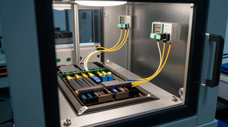
In the realm of OEM/ODM optics, quality assurance is not merely a final inspection but a comprehensive lifecycle of stress testing designed to simulate years of field operation in high-density data centers. Ensuring that custom modules like 400G QSFP-DD or 800G OSFP can withstand extreme thermal fluctuations and electrical stress is critical for maintaining network uptime and preventing costly field failures.
Standard Compliance: Telcordia GR-468
The industry benchmark for optoelectronic reliability is Telcordia GR-468-CORE. This standard defines the generic reliability assurance requirements for devices used in telecommunications equipment, focusing on endurance under environmental stress. For an ODM, adherence to these tests ensures that the mechanical and optical integrity of the transceiver remains uncompromised over its expected service life.
| Test Category | Parameters | Objective |
|---|---|---|
| High-Temperature Operating Life (HTOL) | 85°C / 2000+ Hours | Accelerates aging to identify infant mortality and long-term wear-out mechanisms. |
| Thermal Cycling | -40°C to +85°C | Evaluates mechanical stress and Coefficient of Thermal Expansion (CTE) mismatches. |
| Damp Heat | 85°C / 85% RH | Tests the integrity of seals and materials against moisture-induced corrosion. |
| ESD Threshold | Human Body Model (HBM) | Ensures the optical and electrical components can survive static discharge events. |
HTOL and Accelerated Aging for Silicon Photonics
High-Temperature Operating Life (HTOL) is particularly vital for ODM services involving advanced silicon photonics and EML (Electro-absorption Modulated Laser) components. By biasing components at elevated temperatures for extended durations, engineers can calculate the 'Mean Time Between Failures' (MTBF). This data is essential for Tier-1 network operators who require a 15-year operational lifespan for their infrastructure.
- What is the importance of Burn-in testing?
Burn-in testing involves operating the optical module at its maximum rated temperature and voltage for 24 to 72 hours. This process is designed to weed out components with latent defects before the product is shipped. - How do ODMs validate non-hermetic designs?
Modern silicon photonics often use non-hermetic packaging. ODMs validate these using Temperature-Humidity-Bias (THB) testing and specialized epoxy aging tests to ensure the internal waveguides and modulators remain protected from environmental ingress. - Why is signal integrity testing repeated after stress?
Post-reliability testing requires full re-characterization of the eye diagram and bit error rate (BER). This ensures that physical stress (like thermal expansion) hasn't degraded the high-speed electrical traces or shifted the optical alignment.
Firmware and Software Customization
Firmware customization is the critical layer that ensures optical modules are not only physically compatible but also logically compliant with the host system's operating system. In the OEM/ODM landscape, this involves sophisticated programming of the non-volatile memory and fine-tuning diagnostic parameters to match specific network architecture requirements, ensuring that generic hardware performs like a native component.
EEPROM Coding and Multi-Vendor Interoperability
The EEPROM within an optical transceiver serves as its digital identity, containing metadata such as vendor name, part number, and serial number according to MSA standards like SFF-8472 or SFF-8636. ODM services specialize in 'multi-code' solutions, where the firmware is engineered to respond to I2C queries with specific vendor signatures. This allow modules to bypass 'vendor lock-in' mechanisms in switches and routers from manufacturers like Cisco, Juniper, or Arista, effectively preventing 'unrecognized transceiver' errors and ensuring full functionality of the host's software features.
Advanced Digital Optical Monitoring (DOM) Features
Digital Optical Monitoring (DOM) provides real-time access to operating parameters such as laser bias current, transceiver temperature, and optical transmit/receive power. ODM customization allows for the adjustment of these monitoring thresholds. For instance, in high-density or high-temperature environments, custom firmware can set specific alarm and warning triggers that align with the end-user's unique thermal management strategy, providing more granular control over network telemetry and proactive maintenance.
| Feature | Standard MSA Firmware | Custom ODM Firmware |
|---|---|---|
| Vendor Identification | Generic/Standard MSA | Tailored Vendor ID/Serial Signature |
| Alarm Thresholds | Fixed Factory Settings | User-Defined/Application Specific |
| Host Communication | Standard I2C/MDIO | Optimized Logic for Proprietary OS |
| Telemetry Precision | Basic Resolution | High-Resolution Real-Time Monitoring |
Protocol-Specific Logic and Timing
Beyond identification, custom firmware manages the internal logic of the module to support various communication protocols. Whether it is tuning the clock and data recovery (CDR) for 100G Ethernet or optimizing for Fibre Channel and CPRI/eCPRI in telecommunications, the ODM can modify the transceiver's firmware to handle specific jitter, latency, and synchronization requirements that are not covered by off-the-shelf components.
- How does firmware ensure interoperability?
By emulating the specific memory maps and I2C response sequences required by the host equipment's operating system. - Can ODM firmware support proprietary telemetry?
Yes, custom registers can be defined within the firmware to export specialized health metrics to Software-Defined Networking (SDN) controllers. - Is firmware field-upgradeable?
Most high-quality ODM modules support in-system programming (ISP), allowing firmware updates via the I2C interface to adapt to new switch OS versions.
Supply Chain Resilience and Scalable Manufacturing

Supply Chain Resilience and Scalable Manufacturing
The transition from a prototype optical design to a mass-produced product requires a robust manufacturing infrastructure and a resilient supply chain capable of absorbing market fluctuations. For optical OEM/ODM services, this means moving beyond simple assembly to a holistic management of complex sub-components—such as laser diodes (EML/VCSEL), Digital Signal Processors (DSPs), and integrated circuits (ICs)—while leveraging automation to ensure that the millionth unit produced exhibits the exact same performance characteristics as the first.
Strategic Sourcing of Critical Optical Components
Optical transceivers are highly dependent on a few critical, long-lead components. Effective ODM partners mitigate risks by maintaining strategic relationships with Tier-1 semiconductor and laser foundries. This involves deep visibility into the Bill of Materials (BOM) to identify 'single-source' risks and qualifying alternative components (Second Sourcing) early in the design phase. By managing inventory buffers for high-demand ICs and optical engines, partners can shield customers from the lead-time volatility that frequently plagues the high-tech sector.
| Feature | Manual/Semi-Automated Assembly | Fully Automated High-Volume Lines |
|---|---|---|
| Alignment Precision | Variable (Operator Dependent) | Sub-micron Accuracy (Active Alignment) |
| Throughput | Low (Scales linearly with labor) | High (Scales via equipment cycle time) |
| Yield Consistency | Moderate (Prone to human error) | High (Repeatable process parameters) |
| Traceability | Manual logging / Sampling | Full MES Integration (Unit-level data) |
Automation: The Key to 400G and 800G Scalability
As data rates climb to 400G, 800G, and beyond, the tolerances for optical alignment become incredibly tight—often measured in sub-micron increments. Manual assembly is no longer viable for these speeds. Leading OEM/ODM providers utilize automated die-bonding, gold-wire bonding, and robotic active-optical alignment systems. These systems use real-time feedback to optimize the coupling of light into fibers or waveguides, ensuring maximum signal integrity and minimal insertion loss across every unit.
Supply Chain and Manufacturing FAQ
- How do ODM partners handle global component shortages?
Partners use a combination of strategic inventory buffering, dual-sourcing validation during the NPI (New Product Introduction) phase, and long-term supply agreements with key silicon and laser vendors to ensure continuity. - Why is 'Active Alignment' necessary for high-speed optics?
Active alignment involves powering the laser during the assembly process to find the physical position that yields the highest optical power output. This is critical for 100G+ components where even a 1-micron deviation can significantly degrade performance. - What role does a Manufacturing Execution System (MES) play?
An MES provides end-to-end traceability. Every component's batch, the specific machine parameters used during assembly, and the final test results are linked to a unique serial number, allowing for rapid root-cause analysis if field failures occur.
Strategic Advantages: Time-to-Market vs. R&D Costs
Leveraging OEM/ODM services for optical components is a strategic maneuver that replaces the prohibitive costs of specialized R&D and manufacturing infrastructure with a predictable, volume-based cost structure. By utilizing a partner's pre-existing intellectual property and validated manufacturing processes, companies can launch sophisticated optical products in months rather than years, significantly increasing their competitive edge in fast-moving markets like 5G infrastructure and hyperscale data centers.
The Economic Calculus: Internal R&D vs. OEM/ODM Models
Building a high-end optical product from scratch involves immense CAPEX, including the construction of ISO-certified cleanrooms, the purchase of automated sub-micron alignment systems, and the hiring of specialized photonics PhDs. For many organizations, the 'buy vs. build' decision favors the OEM/ODM model because it converts these massive fixed costs into variable costs (OPEX), allowing for more flexible budget allocation.
| Feature | In-House Development | OEM/ODM Partnership |
|---|---|---|
| Initial Investment | High (Equipment, Facilities, Talent) | Low (NRE Fees, Prototype Costs) |
| Development Timeline | 18–36 Months | 4–9 Months |
| Technical Risk | High (R&D Failure, Yield Issues) | Low (Proven Reference Designs) |
| Unit Economics | High fixed overhead per unit | Volume-optimized pricing |
| Scaling Velocity | Limited by physical capacity | Elastic, global manufacturing reach |
Accelerating Time-to-Market (TTM)
In the optical networking industry, being first to market with a new form factor—such as QSFP-DD or OSFP—can define market share for a decade. ODM partners provide a library of 'Reference Designs' that are already 80% complete. The remaining 20% is customized to the client's specific firmware, labeling, and performance requirements. This modular approach bypasses the 'valley of death' in product development where projects often stall due to unforeseen signal integrity or thermal management issues.
Business Logic and Strategic Questions
- How does an ODM partner reduce technical debt?
By utilizing field-proven optical engines and circuit layouts, ODMs eliminate the iterative 'trial and error' phase of engineering, ensuring the product is built on a stable, high-yield foundation. - Can OEM/ODM help with global compliance?
Yes. Top-tier ODM partners maintain pre-existing certifications for CE, FCC, and RoHS, and have established relationships with testing labs to fast-track regulatory approvals for custom designs. - What is the impact on the supply chain?
ODMs aggregate demand across multiple clients, providing them with superior bargaining power for raw materials like laser diodes and DSP chips, which ensures lower costs and better stock availability during shortages.
Navigating the complexities of optical manufacturing requires a partner with deep technical expertise and a proven track record. By leveraging OEM and ODM services, companies can achieve unmatched network performance while maintaining cost efficiency. Ready to elevate your network infrastructure? Contact our engineering team today for a consultation on your custom optical requirements.